Method and device for measuring axial gaps of differential confocal lens set
A differential confocal and axial gap technology, applied in the direction of measuring devices, optical devices, instruments, etc., to achieve the effect of achieving tomographic capability, high stability, and improving measurement accuracy
- Summary
- Abstract
- Description
- Claims
- Application Information
AI Technical Summary
Problems solved by technology
Method used
Image
Examples
Embodiment 1
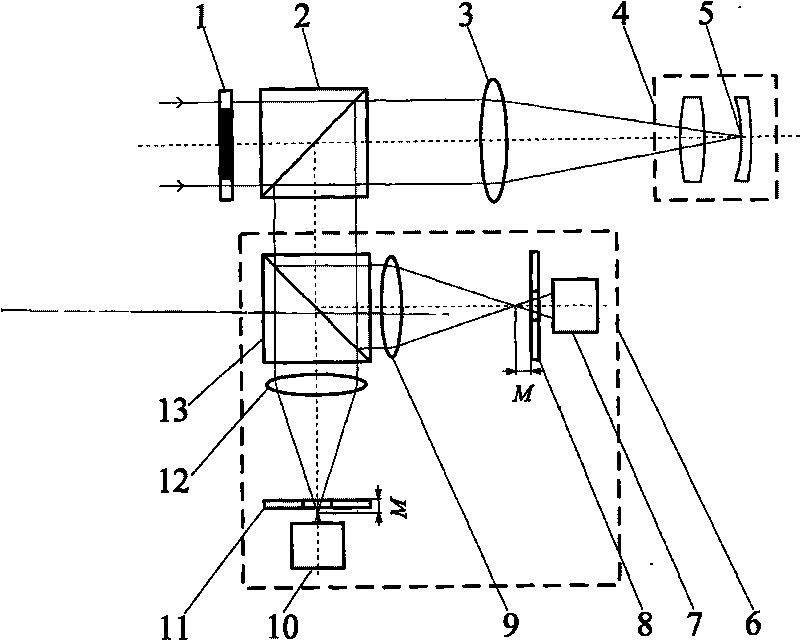
[0051] Such as figure 2 , Figure 5 and Figure 7 As shown, the axial gap measurement method of the differential confocal lens group, the measurement steps are:
[0052] At first, start the measurement software in the main control computer 33, input the design parameters of the mirror group 4 under test, including the radius of curvature of each lens in the mirror group, from left to right: r 1 =195.426mm, r 2 =-140.270mm, r 3 =-140.258mm, r 4 =-400.906mm; Refractive index, from left to right: n 0 = 1, n 1 = 1.5143, n 2 = 1, n 3 = 1.668615.
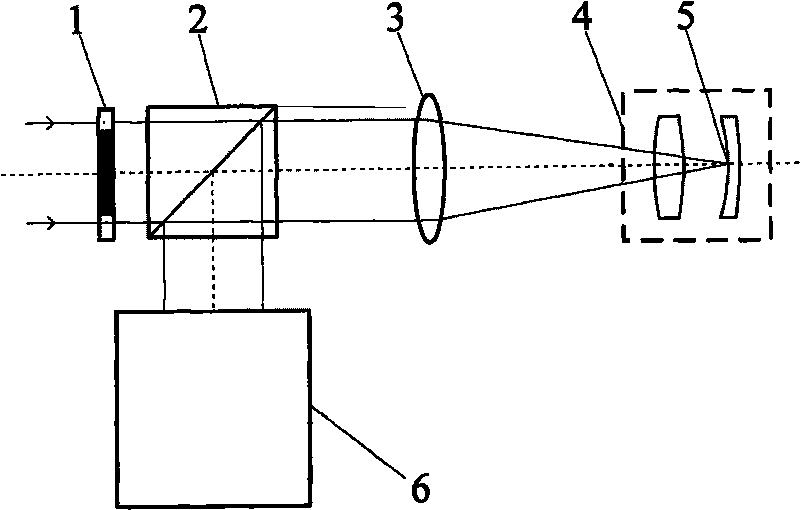
[0053] Then, turn on the collimated light source 26, and the parallel light emitted by it passes through the annular pupil 1 with a light transmission diameter of 6.8mm-9.6mm, passes through the beam splitting system 2, and converges at the focal point 5 through the objective lens 3 with a top focal length of 35mm. A hollow light cone is formed, and the light is reflected by the surface of the inner lens of the mirror group 4 u...
Embodiment 2
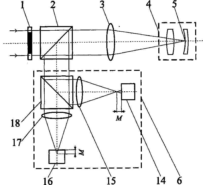
[0064] Such as image 3 , Figure 5 and Figure 7 As shown, the embodiment one figure 2 The differential confocal system in is replaced by image 3 The differential confocal system in the above can constitute the second embodiment. The difference from Embodiment 1 is that after the light enters the differential confocal system 6, the beam splitter 18 divides the light into two paths, the transmitted light illuminates the pre-focus CCD detector 16 after passing through the first lens 17, and the reflected light passes through the second lens The back 15 illuminates the back focus CCD detector 14 . The remaining measurement methods and devices are the same as those in Example 1.
Embodiment 3
[0066] Such as Figure 4 , Figure 5 and Figure 7 As shown, the embodiment one figure 2 The differential confocal system in is replaced by Figure 4 The differential confocal system in the above can constitute the second embodiment. The difference from Embodiment 1 is that after the light enters the differential confocal system 6, the beam splitter 25 divides the light into two paths, and the transmitted light passes through the first lens 24 and the pre-focus microscopic objective lens 23 and passes through the first CCD detector 22. The surface is imaged, and the reflected light is imaged on the surface of the second CCD detector 19 after passing through the second lens 21 and the after-focus microscopic objective lens 20 . The remaining measurement methods and devices are the same as those in Example 1.
[0067] This embodiment realizes the non-contact high-precision measurement of the axial gap in the mirror group through a series of measures, realizes the method an...
PUM
 Abstract
Description
Claims
Application Information
 - R&D
- Intellectual Property
- Life Sciences
- Materials
- Tech Scout
- Unparalleled Data Quality
- Higher Quality Content
- 60% Fewer Hallucinations
Browse by: Latest US Patents, China's latest patents, Technical Efficacy Thesaurus, Application Domain, Technology Topic, Popular Technical Reports.
© 2025 PatSnap. All rights reserved.Legal|Privacy policy|Modern Slavery Act Transparency Statement|Sitemap|About US| Contact US: help@patsnap.com


