Distribution method of third-order intermodulation distortion parameter applied inside receiver radio-frequency system circuit

A third-order intermodulation, radio frequency system technology, applied in the direction of transmission system, electrical components, etc., can solve the problems of strong third-order intermodulation distortion signal, reduce the communication quality of the receiver, difficult to filter, etc., to achieve the effect of ensuring the effectiveness

Active Publication Date: 2010-08-04
BEIHANG UNIV
View PDF2 Cites 5 Cited by
  • Summary
  • Abstract
  • Description
  • Claims
  • Application Information

AI Technical Summary

Problems solved by technology

[0004] The third-order intermodulation distortion signal is a powerful parasitic product that is difficult to filter out, especially when the input signal of the receiver contains two frequencies ω that are close together 1 , ω 2 (Denoted as the front frequency ω 1 , rear frequency ω 2 ), its third-order intermodulation distortion signal frequency Δω(Δω=2ω 1 -ω 2 ) will also be away from ω 1 , ω 2 Close enough to fall within the receive passband, the third-order intermodulation disto

Method used


Image

  • Distribution method of third-order intermodulation distortion parameter applied inside receiver radio-frequency system circuit
  • Distribution method of third-order intermodulation distortion parameter applied inside receiver radio-frequency system circuit
  • Distribution method of third-order intermodulation distortion parameter applied inside receiver radio-frequency system circuit

Examples


Embodiment Construction

[0024] The present invention will be further described in detail below in conjunction with the accompanying drawings and embodiments.

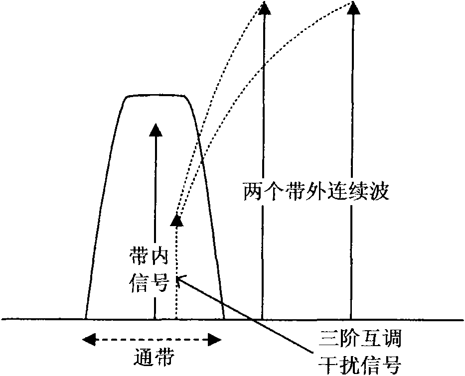
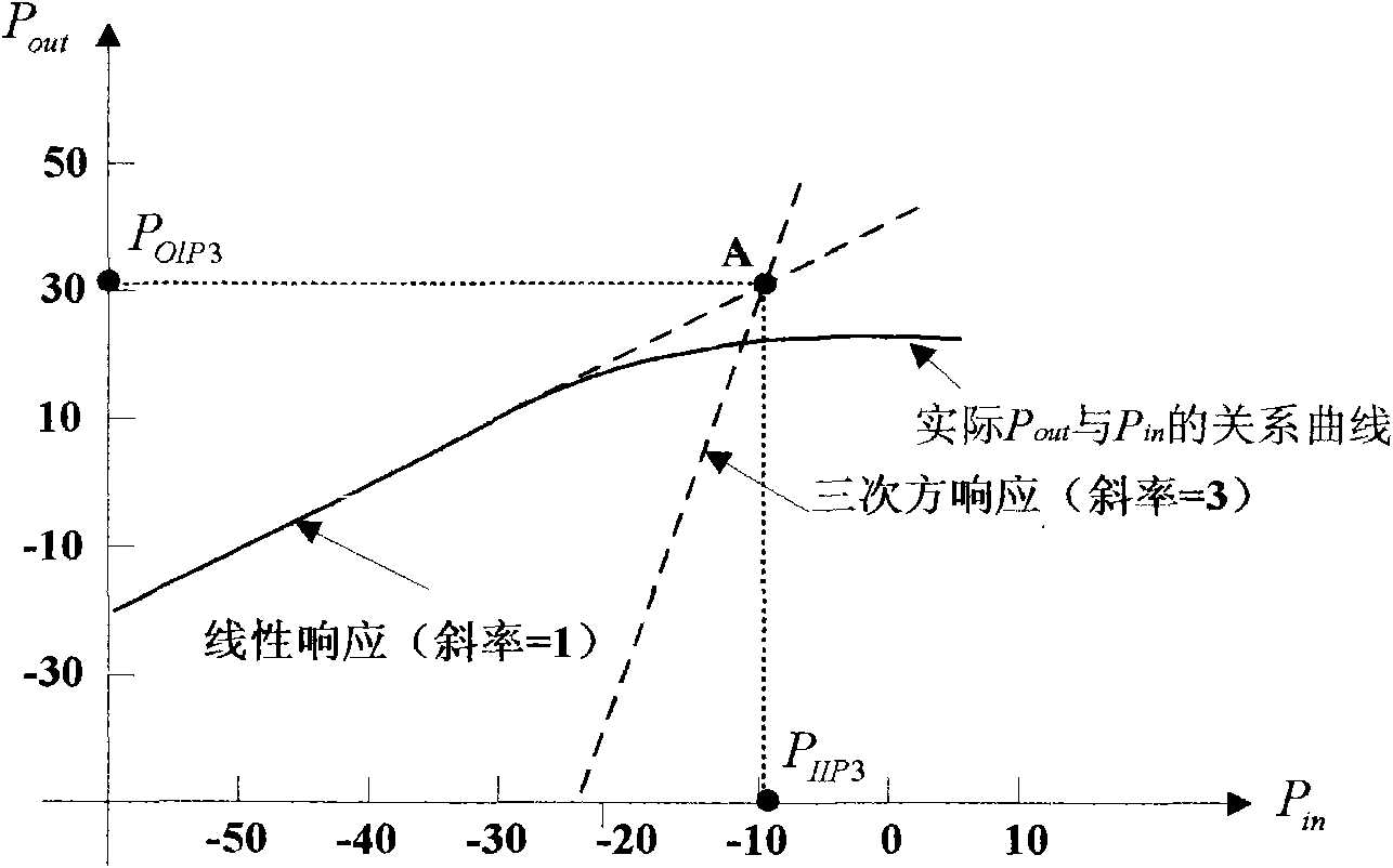
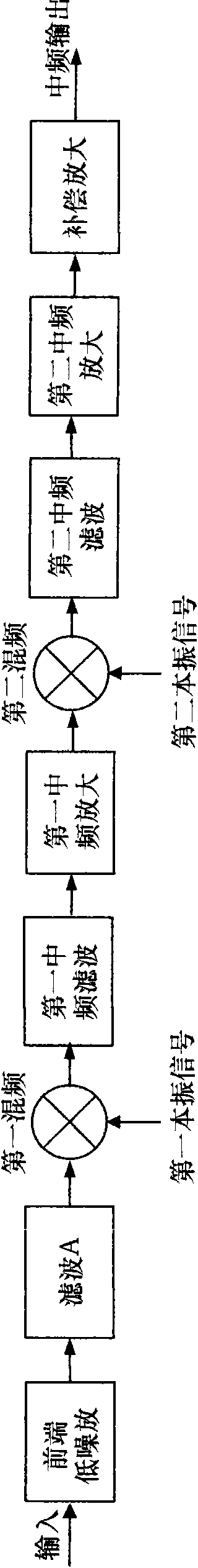
[0025] The invention discloses a method for distributing third-order intermodulation distortion parameters inside a radio frequency system circuit of a receiver, and belongs to the technical field of electromagnetic compatibility. The allocation method first processes the overall receiving performance index of the receiver RF system according to the non-spurious response, and obtains the threshold voltage V′ OIM3 ; Then calculate the third-order intermodulation distortion signal voltage in each level of sub-circuits in the receiving passband that the two interfering continuous waves in the adjacent channel will enter according to the constraint relationship; finally, according to the multi-level total distortion voltage V OIM3 Less than or equal to the threshold voltage V' OIM3 The third-order intercept points of sub-circuits at all levels ar...


PUM


Abstract

The invention discloses a distribution method of third-order intermodulation distortion parameters applied inside a receiver radio-frequency system circuit, which belongs to the technical field of electromagnetic compatibility. The distribution method comprises the following steps: firstly processing the overall receiving performance index of a receiver radio-frequency system according to nonparasitic response to obtain a threshold voltage; then computing the total distortion voltage of third-order intermodulation distortion in each level of sub circuit, which is about to enter a received passband according to constraint relation; and finally obtaining the third-order cut-off point of each level of sub circuit according to the relation that the total distortion voltage is smaller than and equal to the threshold voltage. The method of the invention realizes the distribution of the third-order intermodulation distortion parameters of each level of sub circuit under the condition of cascade circuit voltage signal in-phase, thereby the problem of poor communication quality caused by overlarge third-order intermodulation distortion signal interference of the receiver radio-frequency system is solved.

Description

technical field [0001] The invention relates to a method for allocating third-order intermodulation distortion parameters inside a circuit in a radio frequency system of a receiver. The method solves the interference caused by the third-order intermodulation distortion signal to the receiver, and belongs to the technical field of electromagnetic compatibility. Background technique [0002] The receiver is generally composed of an antenna, a radio frequency system and a demodulation system. The most commonly used superheterodyne receiver radio frequency system includes sub-circuits with nonlinear characteristics such as low noise amplifiers, mixers and intermediate frequency amplifiers. The third-order intermodulation distortion parameter is a very important index of the radio frequency system, and this index determines the power of the generated third-order intermodulation distortion signal. When there are two interfering continuous waves in the receiving adjacent channel, t...

Claims


Application Information

Patent Timeline
IPC IPC(8): H04B1/26H04B1/10
Inventor 苏东林廖意陈文青倪子楠刘焱马超杨柳
Owner BEIHANG UNIV
Why Eureka
Try Eureka