
Photovoltaic energy autonomy system and method of wireless sensor network node

A sensor node, wireless sensor technology, applied in network topology, wireless communication, energy-saving ICT, etc., can solve problems such as insufficient energy management and efficiency utilization, unproven practicability, and inclusion of energy state monitoring, so as to facilitate energy management. , Reduce the number of charge and discharge, and the overall structure is reasonable.

Inactive Publication Date: 2010-08-18
SHANGHAI JIAO TONG UNIV
View PDF4 Cites 23 Cited by
  • Summary
  • Abstract
  • Description
  • Claims
  • Application Information

AI Technical Summary

Problems solved by technology

[0005] After searching, it was found that the Chinese patent application numbers are: 200610114708.5 and 200710117796.9, and the names are respectively: Photovoltaic-temperature difference micro-energy and wireless sensor network node integration autonomous microsystem and a sensor node energy management system. Photovoltaic cells and thermoelectric cells constitute a dual energy conversion system, which makes better use of environmental energy. However, the circuits designed in both technologies manage energy by adding additional microcontrollers and AD converters. The complex design will inevitably result in overall power consumption. Increase, efficiency decrease, there are deficiencies in energy management and efficiency utilization
[0006] After searching, it is also found that the Chinese patent application number is: 200710065331.3, and the name is: an energy supply device and method for wireless network sensor nodes. This technology discloses an energy supply device and method for wireless sensor network nodes, but its disclosure is not Sufficient, the feasibility cannot be proven, and the energy status monitoring is not incorporated into the wireless sensor network system

Method used


Image

  • Photovoltaic energy autonomy system and method of wireless sensor network node
  • Photovoltaic energy autonomy system and method of wireless sensor network node
  • Photovoltaic energy autonomy system and method of wireless sensor network node

Examples


Embodiment

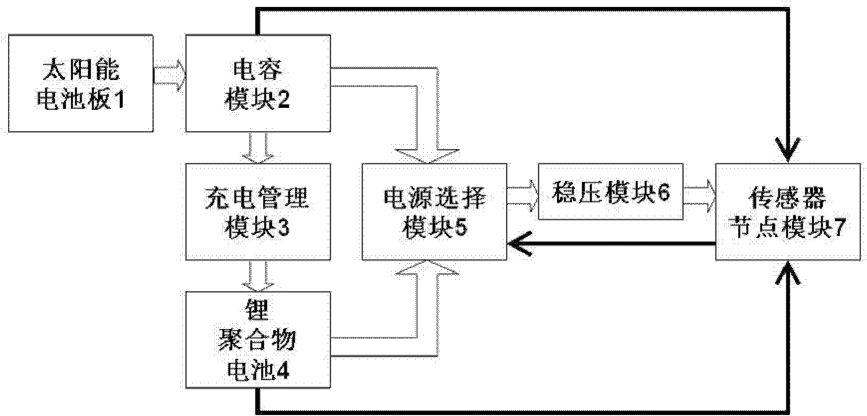
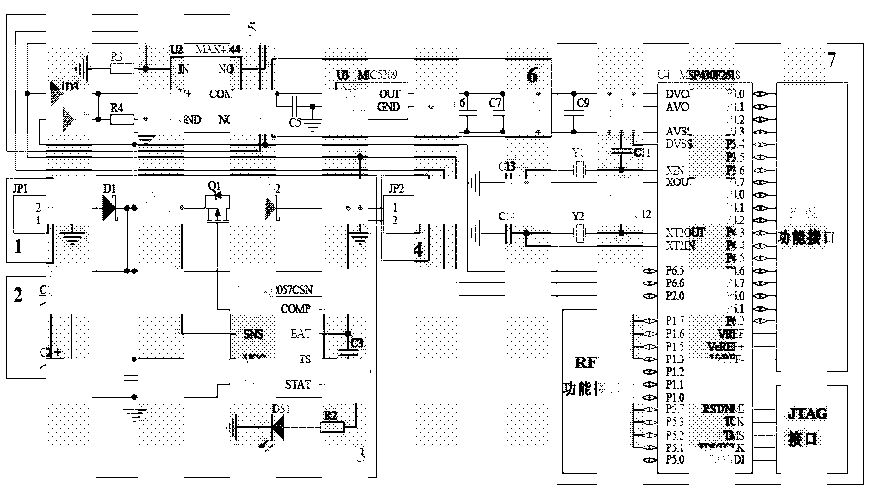
[0023] Such as figure 1 As shown, the wireless sensor network node photovoltaic energy autonomous system involved in this embodiment includes: solar panel 1, capacitor module 2, charging management module 3, lithium polymer battery 4, power supply selection module 5, voltage stabilization module 6 and sensor nodes Module 7, wherein: the solar panel 1 is connected to the capacitor module 2 to transmit energy information, the capacitor module 2 is connected to the charging management module 3 to transmit energy information, the capacitor module 2 is connected to the power supply selection module 5 to transmit energy information, the charging management module 3 is connected to the lithium battery The polymer battery 4 is connected to transmit energy information, the lithium polymer battery 4 is connected to the power selection module 5 to transmit energy information, the power selection module 5 is connected to the voltage stabilizing module 6 to transmit energy information, and ...


PUM


Abstract

A photovoltaic energy autonomy system and method of a wireless sensor network node belong to the technical field of wireless communication. The system comprises an energy storage module, a power selection module, a voltage regulator module and a sensor node module, wherein the energy storage module is connected with the power selection module to transmit energy information; the power selection module is connected with the voltage regulator module to transmit power information; the voltage regulator module is connected with the sensor node module to transmit stable voltage information; the energy storage module is connected with the sensor node module to transmit monitoring information; the sensor node module is connected with the power selection module to transmit control information; and the energy storage module comprises a solar panel, a capacitor module, a charging management module and a lithium polymer battery. The invention can effectively reduce charge-discharge frequency, prolong the service life of the node, ensure simple integral circuit design and lower the energy loss.

Description

technical field [0001] The present invention relates to a system and method in the technical field of wireless communication, in particular to a wireless sensor network node photovoltaic energy autonomous system and an autonomous method thereof. Background technique [0002] Since the wireless sensor network research was put forward in the late 1990s, it has attracted great attention from the military departments, industry circles and academic circles of various countries because of its huge application value. Compared with the traditional network system, the large-scale, random layout, multi-hop communication mode, self-organization and cooperative work of the wireless sensor network make it have broad application prospects in many fields such as military, industry, home furnishing, and environment. Most of the wireless sensor network nodes are placed randomly, and due to the harsh environment or node movement, each node is generally powered by a disposable battery. Once pl...

Claims


Application Information

Patent Timeline
IPC IPC(8): H04W84/18H01M10/42
CPCY02E60/12Y02B60/50Y02D30/70Y02E60/10
Inventor 刘成良李楠刘海宁李彦明
Owner SHANGHAI JIAO TONG UNIV
Learn More