Resource tail gas treatment system and technology for soil vapor extraction repair technique

A gas-phase extraction and treatment process technology, applied in the field of soil remediation, can solve problems such as environmental risks, high heat treatment costs, and increased greenhouse gas emissions, and achieve the effects of simple absorption methods, simple device structures, and increased economic value

Active Publication Date: 2012-05-30
TIANJIN UNIV
View PDF0 Cites 0 Cited by
  • Summary
  • Abstract
  • Description
  • Claims
  • Application Information

AI Technical Summary

Problems solved by technology

Among them, the adsorption process mostly uses activated carbon adsorption technology, but due to its limited adsorption capacity, it is only used for tail gas treatment with low pollutant concentration, and the activated carbon after adsorbing pollutants must be regenerated or post-treated
Heat treatment technology includes on-line combustion and thermal oxidation (such as catalytic oxidation) technology. Its advantage is that the tail gas is completely oxidized and decomposed without subsequent treatment or disposal. It can be used for tail gas treatment with high pollutant concentration, but the cost of heat treatment is high. Electric power Increased control costs, and may increase greenhouse gas emissions, resulting in secondary pollution
Neither of these two technologies has achieved recovery and recycling of pollutants, or there are environmental risks

Method used


Image

  • Resource tail gas treatment system and technology for soil vapor extraction repair technique
  • Resource tail gas treatment system and technology for soil vapor extraction repair technique

Examples


Embodiment 1

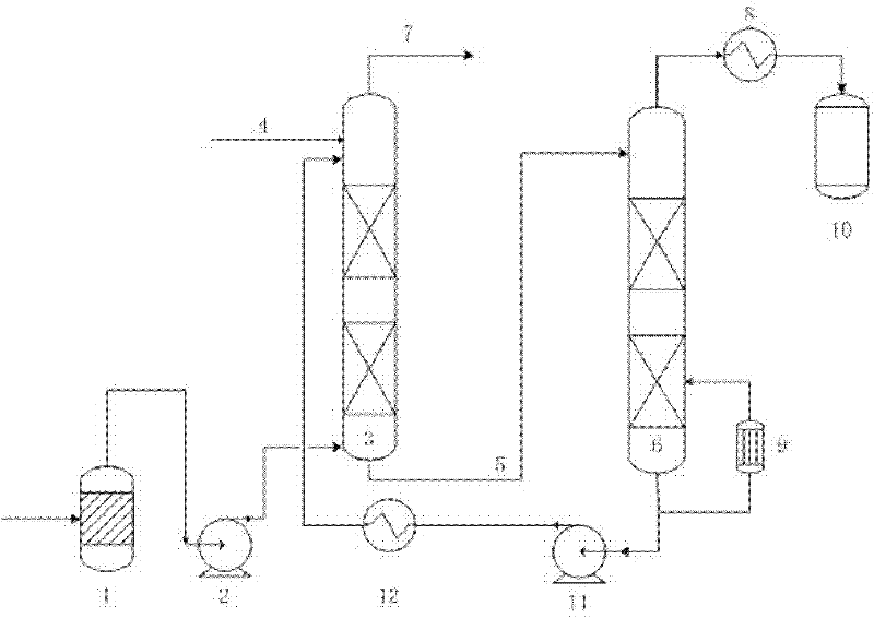
[0024] The tail gas extracted by the gas phase extraction device contains pollutants benzene, toluene and xylene, and the concentration of pollutants is 100mg / m 3 , the extraction flow rate is 200m 3 / h for example. Obtain result as follows according to above-mentioned process embodiment:

[0025] Original pollutant content

Embodiment 2

[0027] The tail gas extracted by the gas phase extraction device contains pollutants benzene, toluene and xylene, and the concentration of pollutants is 300mg / m 3 , the extraction flow rate is 600m 3 / h for example. Obtain result as follows according to above-mentioned process embodiment:

[0028] Original pollutant content

[0029] It can be seen from the above process that the present invention has made an invention and innovation for the treatment of high-concentration pollutant tail gas in the process of gas-phase extraction and restoration of soil. It uses high-efficiency absorbent to absorb, and the absorption rate can reach 99.99%, and the content of organic pollutants in the air fully meets the national regulations. The pollution discharge standard solves the problem of air pollution. In addition, the volatile organic pollutants can be effectively recovered, and the recovery rate can reach more than 99.9%, and the solvent can be recycled, and the regenera...


PUM


Abstract

The invention relates to a resource tail gas treatment system and a technology for a soil vapor extraction repair technique. First, tail gas enters a gas-liquid separation tank. The back of the separation tank is connected with a vacuum pump. The tail gas enters a solvent absorption tower from the output end of the vacuum pump. Gas from which pollutants are removed is exhausted to atmosphere fromthe top of the absorption tower. Solvent by which the pollutants are absorbed is discharged from the bottom of the absorption tower and enters a solvent regeneration tower. The pollutants are discharged from the top of the solvent regeneration tower and enter a pollutant recovery tank after the pollutants are cooled by a condenser. The solvent is delivered by the vacuum pump from the bottom of the regeneration tower to the absorption tower for recycling after the solvent is cooled by the condenser. If high-selectivity absorbent is used under proper operating conditions, the absorption rate ofvolatile or semi-volatile organic pollutants in the tail gas can reach 99.99 percent, the content of organic pollutants in air can fully satisfy the national pollutant discharge standard and the trouble in tail gas treatment related to SVE oil repair is solved. Organic matters are resourced and recovered, the solvent is recycled and the regeneration rate can reach 99.999 percent above.

Description

technical field [0001] The invention relates to the technical field of soil remediation, in particular to a gas phase extraction and remediation technology (SVE) recyclable tail gas treatment system and process. Background technique [0002] Soil vapor extraction (Soil Vapor Extraction, SVE), an emerging soil in situ remediation technology. Because of its effectiveness and extensiveness in the treatment of petroleum-contaminated soil and groundwater, it is gradually developing into a standard environmental restoration technology. It is listed as a "revolutionary technology" by the US Environmental Protection Agency (EPA) and vigorously advocates its application. [0003] Soil Vapor Extraction (SVE) is a common method for physically removing volatile organic compounds (VOCs) and petroleum hydrocarbons from seepage or unsaturated areas (i.e., the area between the surface and the water layer). Organic compounds slowly seep into the area from infiltration points or other sourc...

Claims


Application Information

Patent Timeline
Patent Type & Authority Patents(China)
IPC IPC(8): B01D53/18B01D53/14
Inventor 隋红张瑞玲李鑫刚曹兴涛
Owner TIANJIN UNIV
Why Eureka
Try Eureka