
Micro fluid control chip and preparation method and application thereof

A microfluidic chip and flow channel technology, applied in the field of microfluidics, can solve the problems of difficult control of liquid flow rate, complex chip processing, low mixing efficiency, etc., achieve stable flow rate, good detection effect, and improve mixing efficiency

Inactive Publication Date: 2010-09-01
HUNAN UNIV
View PDF8 Cites 62 Cited by
  • Summary
  • Abstract
  • Description
  • Claims
  • Application Information

AI Technical Summary

Problems solved by technology

However, there are many problems in the existing method of accelerating the mixing of solutions in the chip, such as complex chip processing, low mixing efficiency, need for external power, relatively high cost, etc.
[0004] There are many kinds of drive pumps that can be used for fluid drive in microfluidic chips, such as centrifugal force drive system, pressure drive system, pneumatic micropump, electrostatic micropump, thermopneumatic power micropump and piezoelectric micropump, etc., but most of them The drive pumps are configured separately from the microfluidic chip, and then connected to the microfluidic chip. The flow rate is also difficult to control

Method used


Image

  • Micro fluid control chip and preparation method and application thereof
  • Micro fluid control chip and preparation method and application thereof
  • Micro fluid control chip and preparation method and application thereof

Examples


Embodiment 1

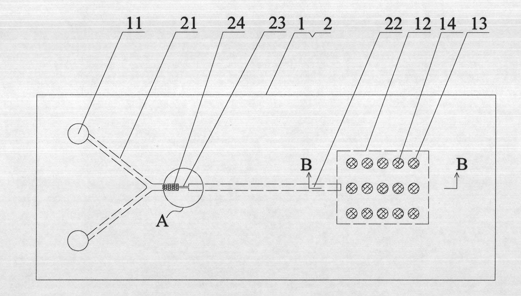
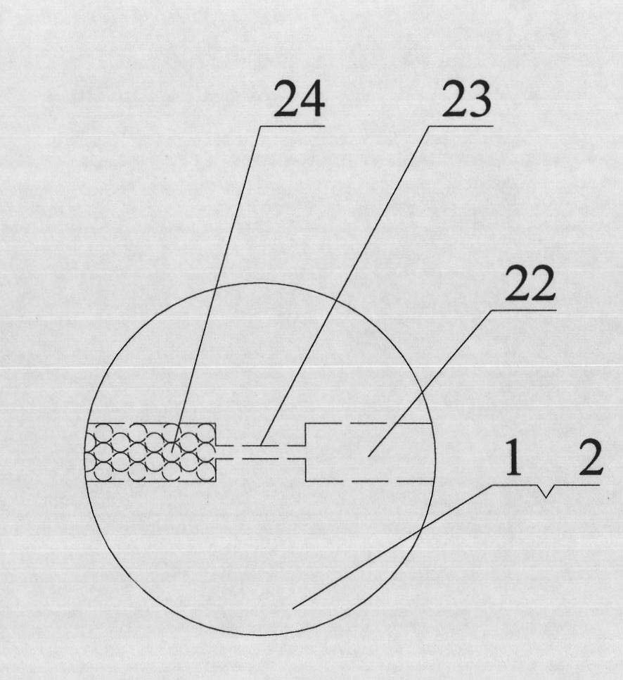
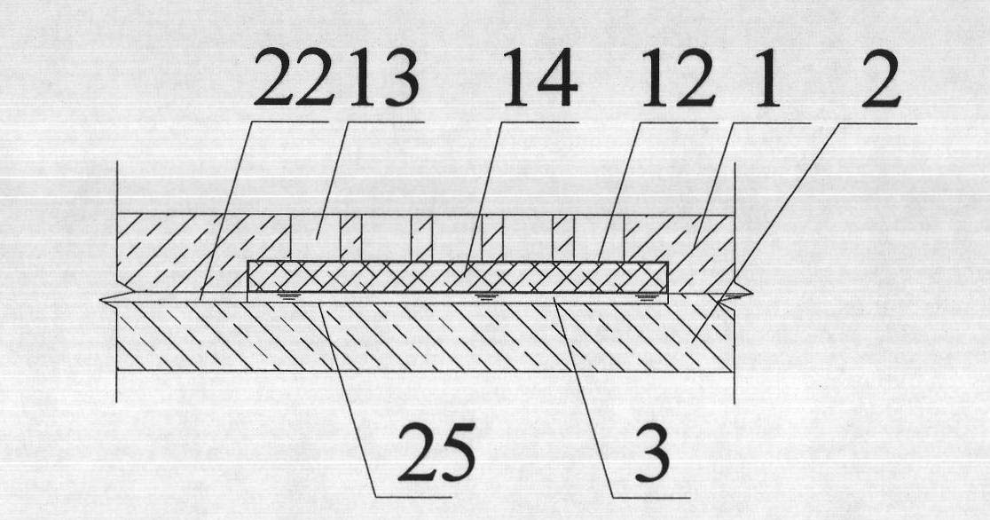
[0038] a kind of like Figure 1 ~ Figure 3 The shown microfluidic chip of the present invention includes a cover sheet 1 and a substrate 2 bonded to each other. The left side of the microfluidic chip is provided with two injection holes 11 with a diameter of 2 mm. Each injection hole 11 It is connected with a sample injection flow channel 21, and each sample injection flow channel 21 is connected to a main flow channel 22 after they meet. Flow channel 23, the narrow flow channel 23 has a width of 15 μm, and the main channel 22 before the entrance of the narrow flow channel 23 is filled with 1 mm long microbeads 24, and the microbeads 24 are made of bovine serum albumin-coated silica material Microbeads, microbeads 24 have a particle size of 20 μm; the substrate 2 is provided with a groove 25 as a waste liquid pool 3, and the outlet of the main channel 22 is connected to the waste liquid pool 3, and the cover sheet above the waste liquid pool 3 1 corresponds to an upper groove...

Embodiment 2

[0054] Nucleotide Fragmentation Sense (NTFS for short) was used to detect different concentrations of ATP in the microfluidic chip fabricated in Example 1 of the present invention.

[0055] The basic principle of the NTFS method is as follows Figure 10 As shown, this method relies on the high dependence of T4 DNA ligase on ATP; in the absence of ATP, nucleic acid fragment A (Oligo A) and nucleic acid fragment B (Oligo B) cannot completely bind to the loop site of the molecular beacon , the molecular beacon cannot be fully turned on, and no fluorescence-enhanced signal is produced. In the presence of ATP, T4 DNA ligase is activated by adenylation to form a ligase-AMP complex. The activated ligase uses the molecular beacon as a template to connect two short fragments of DNA, and the ligation product will be the molecular beacon On, produces a fluorescence-enhanced signal.

[0056] The specific steps for detecting the ATP concentration by using the NTFS method are as follows: ...


PUM

PropertyMeasurementUnit
lengthaaaaaaaaaa
pore sizeaaaaaaaaaa
pore sizeaaaaaaaaaa

Abstract

The invention belongs to the technical field of micro fluid control, particularly disclosing a micro fluid control chip and a preparation method and application thereof. One side of the chip is provided with a plurality of sample introduction holes, each sample introduction hole is communicated with a sample introduction runner; after meeting, each sample introduction runner is communicated with a main runner; the main runner is provided with a narrow runner; a micro-sphere of which the size is 0.5-1.5 mm is filled in front of the inlet of the narrow runner; the outlet of the main runner is communicated to a waste liquid tank arranged at the other side of the chip. The preparation method mainly comprises: firstly preparing a PDMS substrate; then, preparing a PDMS cover plate with an upper groove; sticking the substrate onto the cover plate to obtain a semi-finished product of the chip; carrying out modified treatment on each runner in the semi-finished product of the chip; finally, putting the micro-sphere in, controlling the charge quantity, and finishing production. The micro fluid control chip of the invention has high solution mixing efficiency, stable solution flow rate, small volume, convenient carrying and relatively simple manufacturing; when being used for detecting the density of triphosadenine, the micro fluid control chip has the advantages of high sensitivity, favourable detection effect and the like and can not be affected by environment humidity.

Description

technical field [0001] The invention belongs to the field of microfluidic technology, and in particular relates to a chip based on microfluidic technology, its preparation method and its application in the detection of specific substance concentration. Background technique [0002] With the continuous advancement of science and technology, biochemical analysis is required to develop in the direction of smaller volume, faster response and higher sensitivity. On the basis of this requirement, Manz and Widmer first proposed the concept of micro-total analysis system (μ-TAS) in the early 1990s. In the following ten years, this field has developed into one of the most cutting-edge scientific and technological fields in the world, and its core technology is the microfluidic chip based on microfluidics. Due to the characteristics of miniaturization and integration, microfluidic chip technology can concentrate multi-step operations on one chip, simplify the operation process, and r...

Claims


Application Information

Patent Timeline
Patent Type & Authority Applications(China)
IPC IPC(8): B81B7/00B81C3/00G01N21/64
Inventor 王柯敏羊小海于虹王青
Owner HUNAN UNIV
Learn More