Laser radar launcher based on laser scanning fiber coupling system

A fiber-coupled, laser radar technology, used in radio wave measurement systems, instruments, etc., can solve the problems of low transmittance, slow scanning speed, and small inertia of the scanning system, achieving simple principle, large scanning range, and strong seismic performance. Effect

Inactive Publication Date: 2010-09-01
DONGYING CITY JIAWEN OPTOELECTRONICS
View PDF4 Cites 9 Cited by
  • Summary
  • Abstract
  • Description
  • Claims
  • Application Information

AI Technical Summary

Problems solved by technology

In the acousto-optic deflection, the frequency of the carrier frequency changes. After passing through the acousto-optic deflector, the diffraction angle of the outgoing beam changes with the change of the loaded carrier frequency. The efficiency of the acousto-optic scanner is high, but the scanning speed is relatively slow. slow
Holographic grating scanning is laser scanning based on holography. Its appearance is a great development of laser scanning technology. It is similar to the usual polygon mirror scanning. It requires a mechanical movement to change the deflection of the laser beam, and applies the principle of optical diffraction. Although the holographic grating scan has a large field of view, high efficiency, and small inertia, it is affected by its own low diffraction efficiency, resulting in low transmittance of the entire scanning system

Method used


Image

  • Laser radar launcher based on laser scanning fiber coupling system
  • Laser radar launcher based on laser scanning fiber coupling system
  • Laser radar launcher based on laser scanning fiber coupling system

Examples


Embodiment Construction

[0014] The present invention will be further described below in conjunction with the accompanying drawings and specific embodiments.

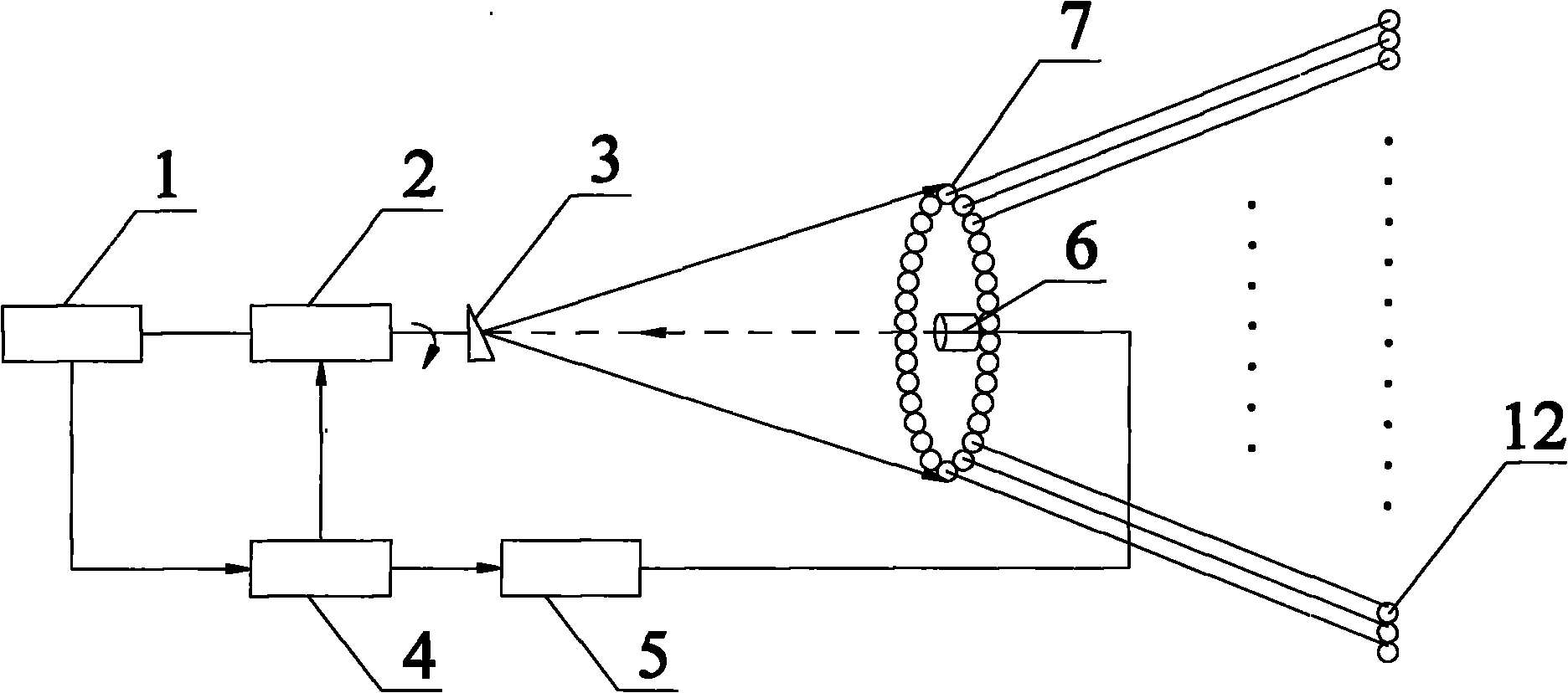
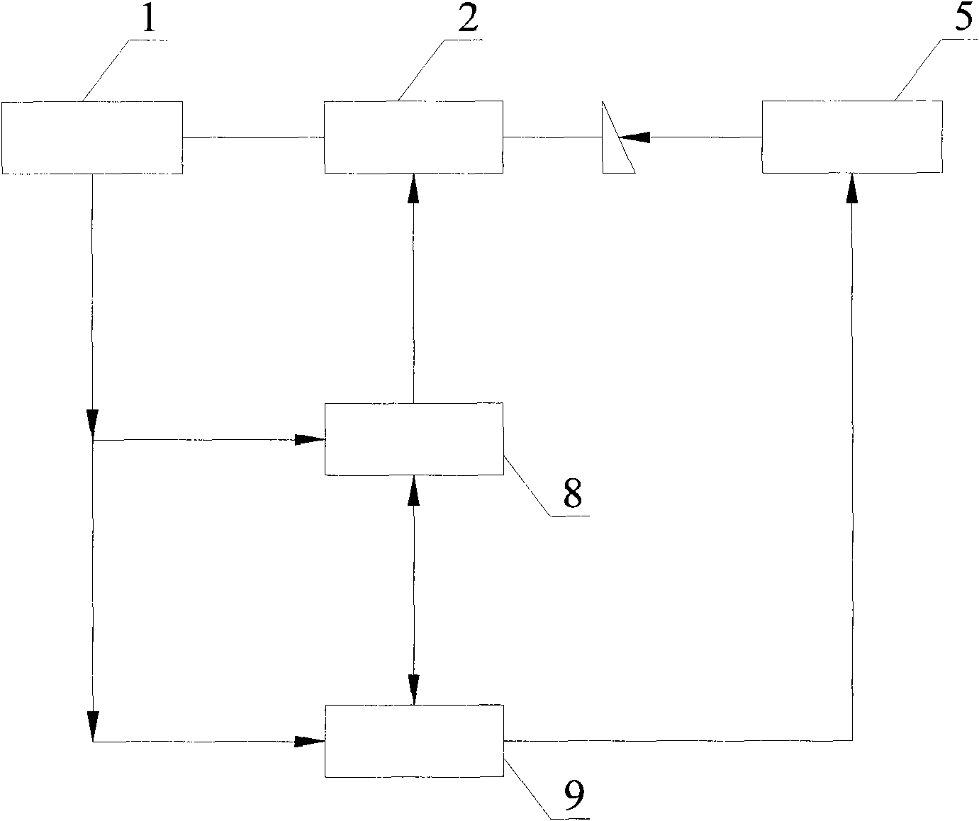
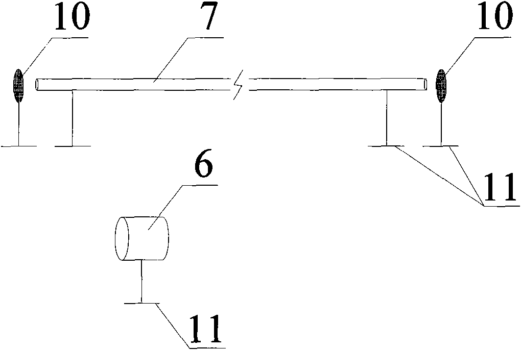
[0015] Such as figure 1 , figure 2 , image 3 As shown, the present invention includes a photoelectric encoder 1, a brushless DC motor 2, a mirror 3, a control subsystem 4, a pulsed fiber laser 5, a collimator 6, an energy transmission fiber 7, and the mirror 3 is at an inclination angle of about 15°. Fixed on one end of the rotating shaft of the brushless DC motor 2, the other end of the rotating shaft is connected to the photoelectric encoder 1 through a flexible coupling, and the collimator 6 on the same axis as the rotating shaft is connected to the pigtail of the pulsed fiber laser 5, That is to say, the photoelectric encoder 1, the rotating shaft of the brushless DC motor 2, the reflector 3, and the collimator 6 are coaxial in space, and there are 90 energy-transmitting optical fibers 7 in total, and the interval between each two is 4°...


PUM


Abstract

The invention relates to a laser radar launcher based on a laser scanning fiber coupling system. A photoelectric encoder and a reflector are respectively connected to the rotating shaft of a brushless DC motor; a collimator in the same axis with the rotating shaft is connected to the tail fiber of a pulse fiber laser device; the end surfaces of one ends of energy transmission fibers are arranged into a circle around the axis and are fixed, and the end surfaces of the other ends of the energy transmission fibers are arranged side by side and fixed to form a fiber panel; a control subsystem is respectively connected with the pulse fiber laser device, the brushless DC motor and the photoelectric encoder; and the control subsystem comprises a motor diver with a Hall sensor, and a FRGA (Field Programmable Gate Array). The invention has the benefits of simple principle, large scanning scope which is not less than +/-16 degrees, compact spatial distribution, easy assembly, high earthquake resistance and high comprehensive efficiency, wherein the overall efficiency of the laser device from transmission to an optical system is 0.81.

Description

technical field [0001] The invention relates to a laser radar transmitting device, in particular to a laser radar transmitting device based on a laser scanning fiber coupling system. Background technique [0002] Lidar is an active modern optical remote sensing device that uses lasers as the radiation source. It is the product of the combination of traditional radar technology and modern laser technology. Since the working wavelength of laser radar is very short, which is three orders of magnitude different from that of microwave radar, and laser is monochromatic coherent light, laser radar has extremely high resolution and anti-interference ability, and is widely used in environmental monitoring and military engineering. , scientific research and national economy and other fields. With the development of laser imaging technology, lidar has also become a new research hotspot in aircraft guidance, helicopter collision avoidance, three-dimensional reconstruction of targets, a...

Claims


Application Information

Patent Timeline
Patent Type & Authority Applications(China)
IPC IPC(8): G01S7/484G01S7/481
Inventor 赵宝泉李学成
Owner DONGYING CITY JIAWEN OPTOELECTRONICS
Why Eureka
Try Eureka