Improved semiautomatic flame cutting machine

A flame cutting machine, semi-automatic technology, applied in gas flame welding equipment, welding equipment, metal processing equipment and other directions, can solve the problems of long cycle and high cost, and achieve the effect of light use, cost reduction and reliable use

Inactive Publication Date: 2010-09-08
WUHAN YIYE STEEL STRUCTURE
View PDF2 Cites 12 Cited by
  • Summary
  • Abstract
  • Description
  • Claims
  • Application Information

AI Technical Summary

Problems solved by technology

During the manufacturing process of steel box girder, according to the design and specification requirements, when two steel plates are butted, there is a difference in plate thickness. In order to prevent the stress from changing greatly and causing the stress to be too concentrated, it is necessary to open a transition groove on the thick plate , the minimum slope length of this project is 50mm, the maximum value is 272mm, and the plate thickness difference is 10-34mm. The traditional processing technology i

Method used


Image

  • Improved semiautomatic flame cutting machine
  • Improved semiautomatic flame cutting machine
  • Improved semiautomatic flame cutting machine

Examples


Example Embodiment

[0018] Example 1: Improved semi-automatic flame cutting machine

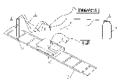
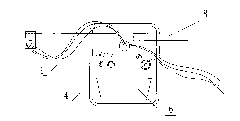
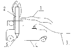
[0019] The structure of the cutting machine is as Figure 1 to Figure 3 Shown: a pair of gas belt 1, an extended gun head 2, a semi-automatic flame cutting machine 4, a 603.6# imported cutting nozzle 5, 25kg counterweight 6, oxygen meter 9, propane meter, and supporting power supply and other components composition. Among them: the liquid oxygen tank 8 is connected with the oxygen meter 9, the oxygen meter is connected by the gas belt 1 and the semi-automatic flame cutting machine 4, and the semi-automatic flame cutting machine 4 is connected by the gas belt 1 and the extended gun head 2. The semi-automatic flame cutting machine is connected to the power supply through the wire 3. The base of the cutting machine can move back and forth on the track 7. The base is equipped with a vertical pipe for conveying gas. The upper part of the pipe is equipped with a cross bar, and one end of the cross bar is equipped with a...

Example Embodiment

[0022] Example 2: Application of an improved semi-automatic flame cutting machine

[0023] The working process of the present invention is:

[0024] 1. Preparation before operation:

[0025] (1) After cutting the steel plate needed for transition beveling, place it on the flat cutting platform.

[0026] (2) The riveter designs the groove form according to the drawing, and marks the line in the thickness direction of the steel plate.

[0027] (3) Choose an experienced gas welding operator.

[0028] (4) Prepare an oxygen meter, a propane meter, a gas belt, a cutting machine, a lengthened gun head, an imported cutting nozzle 603.6#, and a matching power supply.

[0029] 2. Formal operation:

[0030] (1) Place the track smoothly on the steel plate to be cut, adjust the distance between the cutting edge and the track, place the assembled cutting machine on the track and add a counterweight of 25kg.

[0031] (2) Check the oxygen pressure gauge and propane pressure gauge to ensure that the oxygen ...


PUM

PropertyMeasurementUnit
Lengthaaaaaaaaaa

Abstract

The invention discloses an improved semiautomatic flame cutting machine, which comprises a semiautomatic flame cutting machine (4), a liquid oxygen tank (8) and a gun head connected with one another through air belts, wherein the gun head is a prolonged gun head (2) for digital control cutting, the length of the gun head is 450 to 550 mm, and an inlet cutting nozzle (5) connected with the gun head is a divergent inlet cutting nozzle. The improved semiautomatic flame cutting machine is also provided with a rail (7) which is in slide connection with a base of the semiautomatic flame cutting machine (4). The improved semiautomatic flame cutting machine can process a steel box girder groove of the semiautomatic flame cutting machine through the steps of preparation before operation, normal operation and post-operation; besides, the improved semiautomatic flame cutting machine has the advantages of having simple and convenient operation, ensuring the quality, shortening the time limit, reducing the cost and the like, and can replace the conventional mode of processing the groove mechanically.

Description

technical field [0001] The invention relates to the field of groove processing of steel box girders, in particular to an improved groove machine of a semi-automatic flame cutting machine. Background technique [0002] Steel box girder, also known as steel plate box girder, is a commonly used structural form of long-span bridges, and its application is becoming more and more extensive. During the manufacturing process of steel box girder, according to the design and specification requirements, when two steel plates are butted, there is a difference in plate thickness. In order to prevent the stress from changing greatly and causing the stress to be too concentrated, it is necessary to open a transition groove on the thick plate , the minimum slope length of this project is 50mm, the maximum value is 272mm, and the plate thickness difference is 10-34mm. The traditional processing technology is that when the transition groove slope length is greater than 80mm, it needs to be ma...

Claims


Application Information

Patent Timeline
IPC IPC(8): B23K7/00B23K7/10
Inventor 徐圣佳程治南足刚王建成朋
Owner WUHAN YIYE STEEL STRUCTURE
Why Eureka
Try Eureka