
Mounting table structure and plasma film forming apparatus

A mounting table and block technology, which is applied in ion implantation plating, semiconductor/solid-state device manufacturing, coating and other directions, can solve the problems of inability to withstand high temperature, difficult to handle the clean state of the container, and inability to use adhesives, etc. To achieve the effect of high temperature resistance

Active Publication Date: 2010-09-22
TOKYO ELECTRON LTD
View PDF5 Cites 14 Cited by
  • Summary
  • Abstract
  • Description
  • Claims
  • Application Information

AI Technical Summary

Problems solved by technology

[0008] However, with regard to the above-mentioned device example, no particular problem occurred in the prior art in which the design criteria were not so strict. However, as refinement and high integration progress and the design criteria become stricter, the resulting The quality and characteristics of the metal film are required to be higher
For example, for the metal film to be formed, in order to prevent the pollution caused by the mixing of different metals and elements, by vacuumizing the processing container to a high vacuum in advance during the film forming process, the surface or inside of the processing container will be adhered to Impurities such as the surface of the structure are discharged as exhaust gas, but since impurity gases such as siloxane, which is usually a silicon compound, are degassed from the above-mentioned adhesive 14 as exhaust gas, the inside of the processing container cannot be made into a high vacuum state. Therefore, it is difficult to make the inside of the processing container clean
[0009] In addition, in order to improve the quality and characteristics of the film as described above, it is also required to perform film formation at a high processing temperature of, for example, about 400°C. However, the heat-resistant temperature of the above-mentioned adhesive is relatively low, for example, about 80°C. There is a problem that the adhesive cannot be used
[0010] In addition, there is known a mounting table structure formed by embedding a chuck electrode and a heater on the upper surface of the mounting table by thermal spraying. Capable of withstanding high temperatures as above

Method used


Image

  • Mounting table structure and plasma film forming apparatus
  • Mounting table structure and plasma film forming apparatus
  • Mounting table structure and plasma film forming apparatus

Examples


no. 2 example

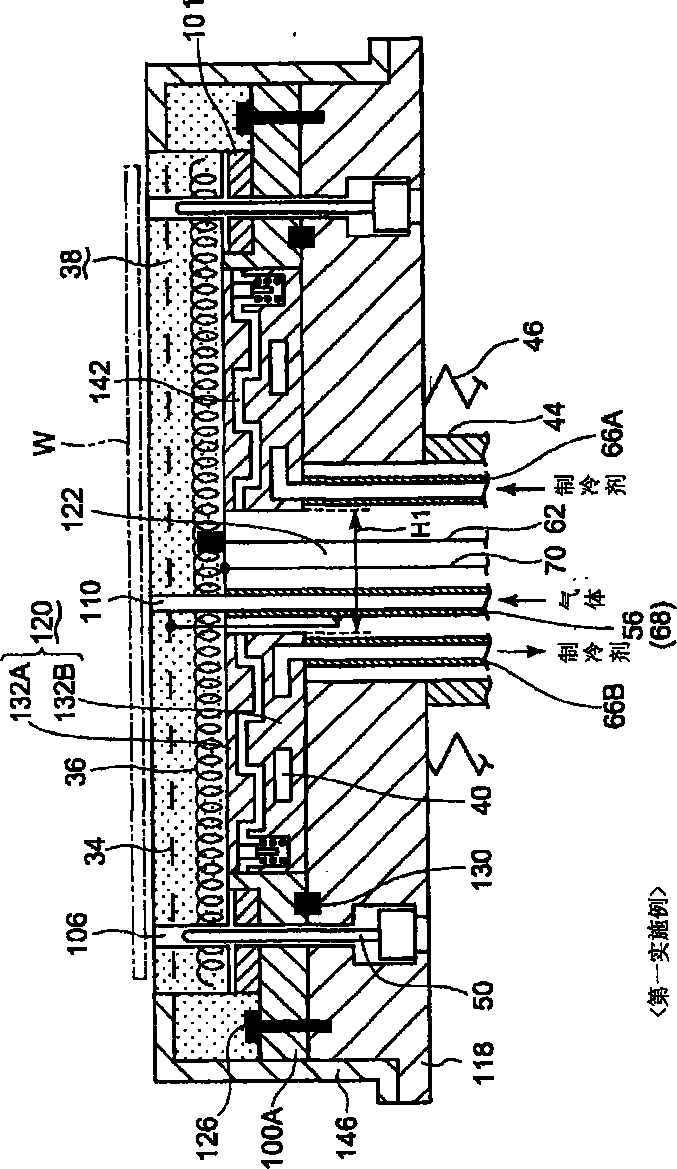
[0121] Next, a second embodiment of the mounting table structure of the present invention will be described. Figure 7 It is an enlarged cross-sectional view of a main part showing a second embodiment of the mounting table structure of the present invention. In addition, in Figure 7 in, with figure 2 Components that are the same as those shown are denoted by the same reference numerals, and description thereof will be omitted.

[0122] In the case of the previous first embodiment, the cooling jacket 120 is divided into two parts up and down, that is, the upper block 132A and the lower block 132B, but not limited thereto, such as Figure 7 As shown, the cooling jacket part 120 may also have an integral structure in which the cooling jacket part 120 is not divided. In this case, a slight gap is provided between the upper surface of the cooling jacket part 120 and the lower surface of the mounting table 38, and a flat gas heat conduction relaxation layer 142 is formed there....

no. 3 example

[0125] Next, a third embodiment of the mounting table structure of the present invention will be described. Figure 8 It is an enlarged cross-sectional view showing the main part of the third embodiment of the mounting table structure of the present invention, Figure 9 It is a graph showing the relationship between the voltage of creeping discharge and the distance of creeping discharge. In addition, in Figure 8 in, with figure 2 Components that are the same as those shown are denoted by the same reference numerals, and description thereof will be omitted.

[0126] In the case of the previous embodiments 1 and 2, for example, between the electrode line 56 to which a DC high voltage of 4,000 volts is applied and the thermocouple line 70 or the feeder line 62 near approximately zero potential, the upper end of each line and the load A creeping discharge in which discharge occurs along the lower surface of the mounting table 38 may occur at the connection portion of the low...


PUM

PropertyMeasurementUnit
diameteraaaaaaaaaa

Abstract

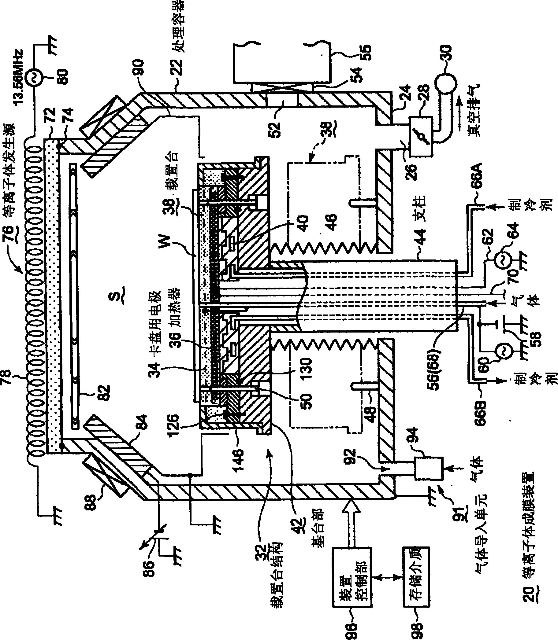
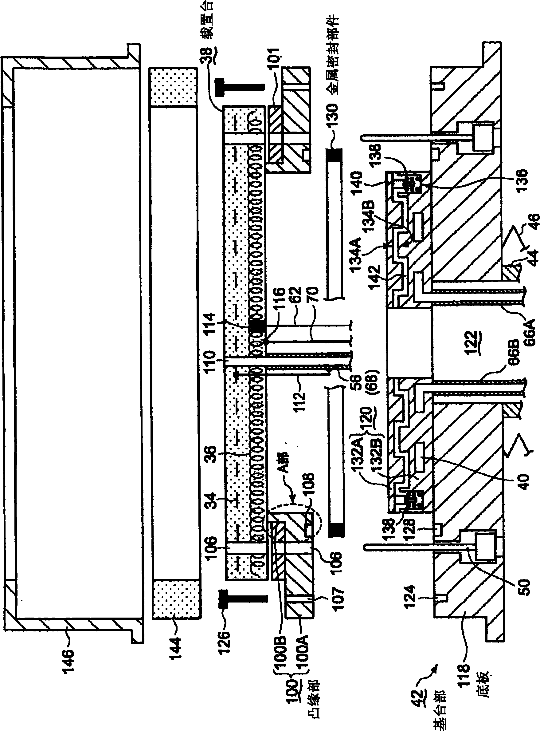
The present invention provides a mounting table structure capable of enduring a high temperature and maintaining at a high vacuum level in a processing chamber by sufficiently performing a degassing treatment. The mounting table structure for mounting thereon an object to be processed to form a metal-containing thin film on the object includes a ceramic mounting table in which a chuck electrode and a heater are embedded, and a metal flange connected to a bottom surface of a peripheral portion of the mounting table. The mounting table structure further includes a metal base which is joined to the flange by screws and has a coolant path for flowing a coolant therein, and a metal seal member interposed between the flange and the base.

Description

technical field [0001] The present invention relates to a plasma film forming apparatus for forming a metal-containing thin film on an object to be processed such as a semiconductor wafer by using plasma, and to a stage structure used in the film forming apparatus. Background technique [0002] In general, in order to manufacture semiconductor devices, various processes such as film formation and pattern etching are repeatedly performed on semiconductor wafers to manufacture desired devices. Apertures are getting finer. In addition, aluminum alloys have been mainly used as wiring materials and embedding materials in the past. However, recently, the line width and hole diameter have become increasingly finer, and high-speed operation speeds are desired. Therefore, tungsten (W) and copper (Cu) have been used. Propensity. [0003] In addition, when using the above-mentioned metal materials such as Al, W, Cu, etc. as the wiring material and the embedding material of the hole f...

Claims


Application Information

Patent Timeline
Patent Type & Authority Applications(China)
IPC IPC(8): H01L21/683H01L21/00
CPCH01L21/68785H01J37/34H01L21/67109C23C14/50
Inventor 藤里敏章R·内斯曼
Owner TOKYO ELECTRON LTD
Learn More