Power system of single-screw expansion engine as pneumatic automobile engine

A pneumatic vehicle and power system technology, applied in the direction of machines/engines, combined engines, intermeshing engines, etc., can solve problems such as difficult control and complex structure of piston pneumatic engines, and achieve simple valve mechanism, small vibration, and easy The effect of control

Active Publication Date: 2010-10-06
江苏京通冷链设备科技有限公司
View PDF4 Cites 7 Cited by
  • Summary
  • Abstract
  • Description
  • Claims
  • Application Information

AI Technical Summary

Problems solved by technology

[0005] The purpose of the present invention is to design a set of highly efficient and feasible engine power system suitable for...

Method used


Image

  • Power system of single-screw expansion engine as pneumatic automobile engine
  • Power system of single-screw expansion engine as pneumatic automobile engine
  • Power system of single-screw expansion engine as pneumatic automobile engine

Examples


Embodiment approach 1

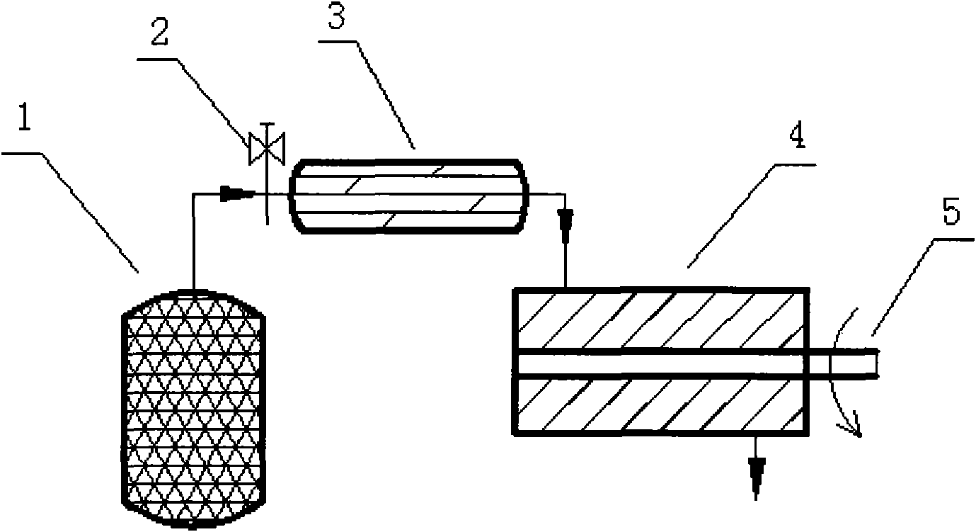
[0019] Scheme system see figure 2 , the present embodiment adopts the form of a single-stage expander, and the heating method can be hot water heating, air heating, or gas heating.

[0020] The pneumatic engine power system includes a high-pressure air bottle 1 used as a power source, a regulating valve 2 for working condition control, a heater 3 and a single-screw motor 4, and the air flowing out of the high-pressure air bottle 1 controls the compressed air through the regulating valve 2 After the flow rate and pressure reach the predetermined working conditions, it enters the heater 3 for heating, so as to increase the working temperature of the compressed air and gain the output work. After that, the pressurized high-temperature air enters the single-screw engine 4 to perform expansion work, and the mechanical work output shaft 5 output mechanical work.

Embodiment approach 2

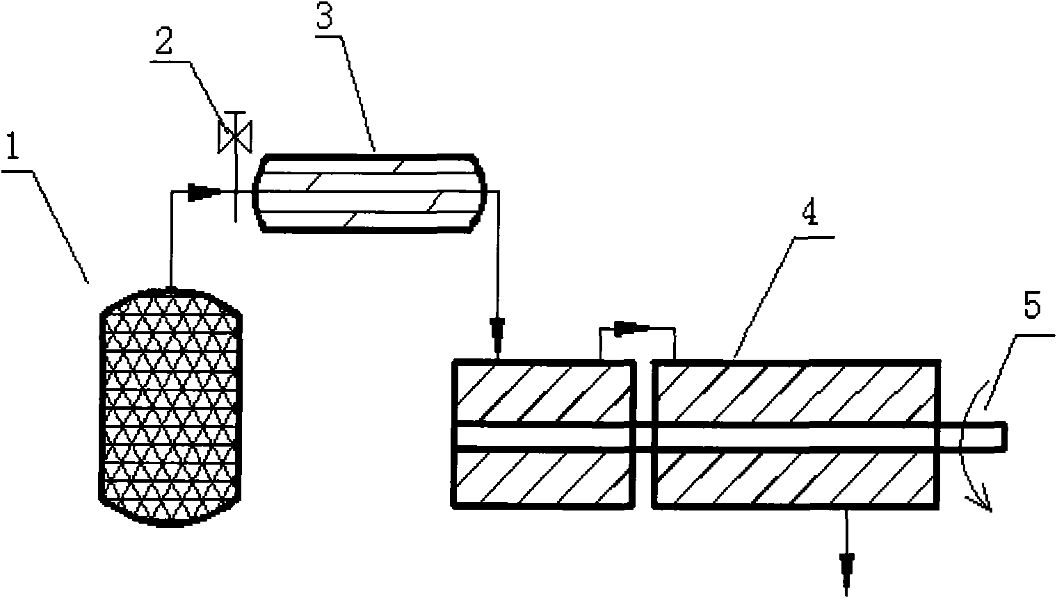
[0022] Scheme system see image 3 , The system of this embodiment adopts the form of two-stage expansion and first-stage heating, and the heating method can be hot water heating, air heating, or gas heating. Since the two-stage system has the optimal expansion ratio at different heating temperatures, it is necessary to select a single-screw expander that matches the corresponding optimal expansion ratio. The two-stage expansion work can increase the total expansion ratio and increase the power output. The connection mode of the two-stage expanders is designed to be in series, that is, the exhaust gas of the first-stage expander is used as the intake air of the second-stage expander, and the Coaxial output makes the structure more compact and easy to control. This system solution is mainly used in engines with medium power.

[0023] The pneumatic engine power system includes a high-pressure air bottle 1 used as a power source, a regulating valve 2 for working condition control...

Embodiment approach 3

[0025] Scheme system see Figure 4 , The system of this embodiment adopts the form of three-stage expansion and hierarchical heating, and the heating method can be hot water heating, air heating, or gas heating. Considering the problem of inter-stage distribution, it is necessary to select the optimal matching of the three-stage expansion ratio, and in order to improve work efficiency, the compressed air is heated before entering each stage of the expander, that is, the way to realize staged heating. The system scheme can realize relatively large power output, and is suitable for relatively high-power automobile engines.

[0026]The pneumatic engine power system includes a high-pressure air bottle 1 used as a power source, a regulating valve 2 for working condition control, a heater 3 and a single-screw motor 4, and the air flowing out of the high-pressure air bottle 1 controls the compressed air through the regulating valve 2 After the flow and pressure of the compressed air...


PUM


Abstract

The invention discloses a power system of a pneumatic automobile engine. The original piston power system of a pneumatic automobile has the defects of easy abrasion, high noise and complicated interlinking mechanism. The power system mainly comprises a high-pressure air bottle (1) as a power source, a regulating valve (2) for realizing control, a heater (3) and a single-screw engine (4). By adopting a single-stage single-screw expansion engine or a multi-stage single-screw expansion engine as a pneumatic engine, the power system has the characteristics of simple structure, low noise, long service life, simple control on the interlinking mechanism of the engine system and continuous and steady operation of an output shaft (5). The single-screw engine comprises a single-stage expansion mode and a multi-stage expansion mode, a multi-stage system connecting mode includes a serial connection form, a parallel connection form and a blend connection form, and the power system has the advantages of flexible and diverse arrangement mode, wider application working range of the engine and easy realization of connection and control. Due to the characteristics of the system, the invention has a great advantage when applied to the pneumatic automobile engine.

Description

technical field [0001] The invention relates to a novel pneumatic engine power system, which belongs to the field of high-tech automobile power. Background technique [0002] With the improvement of people's quality of life, cars have gradually changed from luxury goods to means of transportation. Although this reflects the progress of society and meets people's material needs, it also makes people fall into the trap of limited resources and environmental pollution. Two big problems. Therefore, people have begun to pay more attention to how to eliminate dependence on fossil fuels, and have been longing for the emergence of new "green cars" and green energy for cars. [0003] From the battery-powered EV electric vehicle in the 1930s to the current HEV hybrid electric vehicle and alternative fuel vehicles, the research and development of automotive energy has never stopped, but there are still unsolved problems in each research. Alternative fuel vehicles, such as natural gas...

Claims


Application Information

Patent Timeline
IPC IPC(8): F01C1/18F01C11/00
Inventor 马重芳吴玉庭何为
Owner 江苏京通冷链设备科技有限公司
Why Eureka
Try Eureka