Super-resolution laser polarization differential confocal imaging method and device

A differential confocal, imaging device technology, applied in the direction of using optical devices, measuring devices, instruments, etc., to achieve the effect of improving signal-to-noise ratio, improving linearity, and improving lateral resolution

Active Publication Date: 2010-10-06
BEIJING INSTITUTE OF TECHNOLOGYGY
View PDF3 Cites 58 Cited by
  • Summary
  • Abstract
  • Description
  • Claims
  • Application Information

AI Technical Summary

Problems solved by technology

For example, the Chinese patent "Differential Confocal Scanning Detection Method with High Spatial Resolution" (patent number: 200410006359.6), which proposed a super-resolution differential confocal detection method, made the axial resolution of the system reach the nanometer level, and significantly improved The environmental anti-interference ability is improved, but the differential confocal technology is combined with the radial polarization and pupil filter technology, and the axial resolution is significantly improved by using the differential confocal technology, and the radial polarization and pupil filter technology are used to significantly improve Horizontal resolution, so as to achieve the improvement of spatial resolution, has not been seen so far

Method used


Image

  • Super-resolution laser polarization differential confocal imaging method and device
  • Super-resolution laser polarization differential confocal imaging method and device
  • Super-resolution laser polarization differential confocal imaging method and device

Examples


Embodiment 1

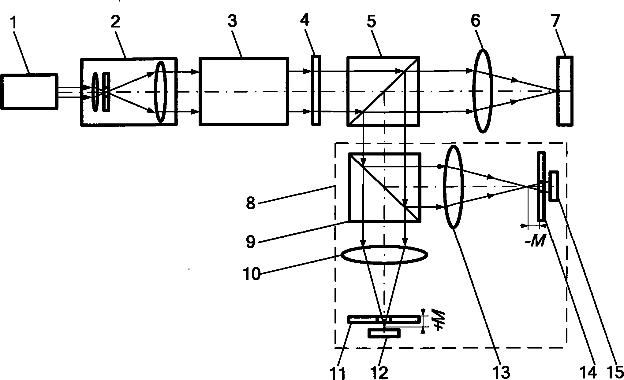
[0048] Such as figure 1 , image 3 , Figure 6 , Figure 7 As shown, a pure phase liquid crystal spatial light modulator is used in combination with a λ / 4 wave plate to generate radially polarized light, and combined with a concentric five-ring binary optical element to filter the radially polarized light, the method of the present invention is adopted Perform microscopic imaging with the device.

[0049] Such as figure 1 As shown, the principle of the super-resolution laser polarization differential confocal imaging method is as follows:

[0050] First, the light emitted from the laser 1 is modulated into radially polarized light by the beam expander 2 and the polarization state modulation system 3, and then focused onto the surface of the sample 7 to be measured by the pupil filter 4, the beam splitter 5, and the objective lens 6, and the surface of the sample 7 The reflected light passes through the objective lens 6 and the beam splitter 5 again, and the reflected ligh...

Embodiment 2

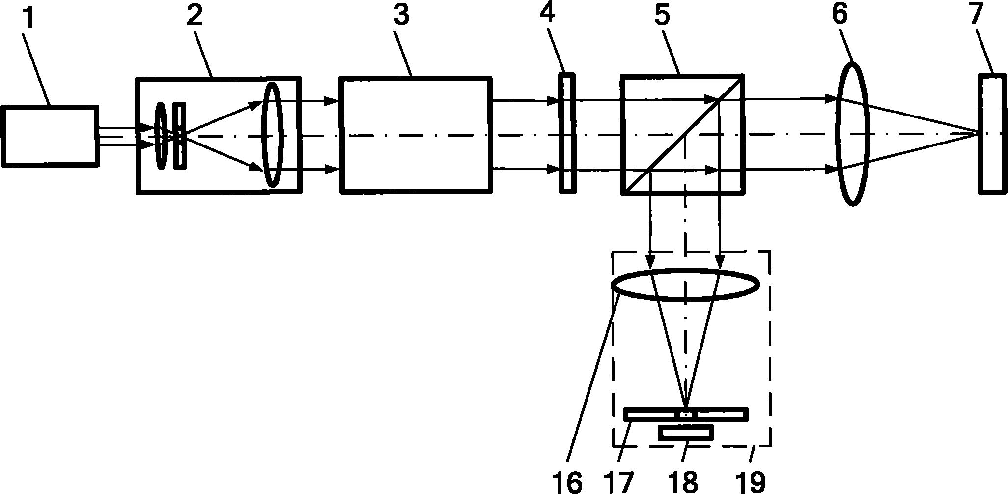
[0065] Such as figure 2 and Figure 8 Shown are schematic diagrams of embodiments of a super-resolution laser polarization differential confocal imaging method and device using a confocal system. Example 1 figure 1 and Figure 7 The differential confocal system in 8 is replaced by figure 2 and Figure 8 The confocal system 19 in the confocal system can constitute the super-resolution laser polarization differential confocal imaging method and device embodiment 2 using the confocal system. The difference from Embodiment 1 is that after the light enters the confocal system 19 , it is focused to the pinhole 17 by the lens 16 and detected by the detector 18 . All the other measuring methods and devices are the same as in Example 1.

[0066] Real-time example 3

[0067] Such as Figure 4 and Figure 7 As shown, the embodiment 1 Figure 7 The polarization modulation system in is replaced by Figure 4 The polarization state modulation system in , can constitute embodimen...

Embodiment 4

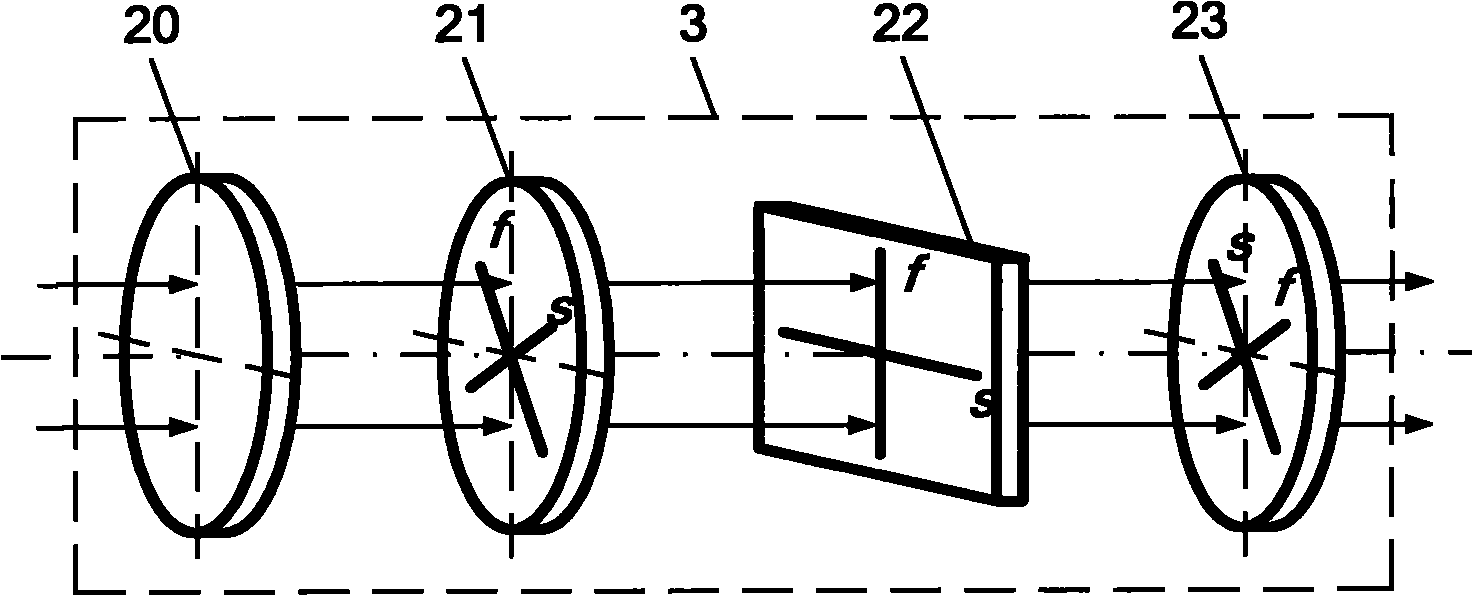
[0069] Such as Figure 5 and Figure 7 As shown, the embodiment 1 Figure 7 The polarization modulation system in is replaced by Figure 5 The polarization state modulation system in can constitute embodiment 4. The difference from Embodiment 1 is that after the light enters the polarization state modulation system 3, the incident laser beam is modulated into linearly polarized light by the polarization modulator 29, and then incident on the block λ / 2 wave plate spatially varying retarder 30 and modulated into a linearly polarized light beam. The polarized light is focused by the focusing lens 31 to the non-confocal Fabry-Perot interferometer 32 for mode selection and obtains radially polarized light with higher purity, which is collimated by the collimator lens 33 and then exits; block λ / 2 wave plate The spatially variable retarder 30 is spliced ​​and combined by 4 or 8 λ / 2 wave plates with identical optical properties, and the included angles between its fast axis (or slo...


PUM


Abstract

The invention belongs to the technical field of optical precision measurement, relating to super-resolution laser polarization differential confocal imaging method and device. The method improves the transverse resolution power by combining a radial polarized light and a pupil filtering technology, improves the axial resolution power by using a differential subtraction detection technology of an axial-offset dual-detector system and remarkably improves the spatial resolution power and tomography ability of the system. The device comprises a laser source as well as a beam expander, a polarization state modulation system, a pupil filter and a spectroscope which are sequentially arranged at a transmitting end of the laser source, an objective and a sample which are arranged in the transmitted light direction of the spectroscope in turn, and a differential confocal system in the opposite direction of the reflected light direction of the spectroscope. The invention combines the radial polarized light resolution technology with the pupil filtering technology and improves the transverse resolution power of the system; moreover, the differential work mode of the invention can remarkably improve the axial imaging ability of the system and is applicable to the high-precision detection and metering of nanometer-level geometrical parameters in the nanometer manufacturing field.

Description

technical field [0001] The invention belongs to the technical field of optical precision measurement, and relates to a super-resolution laser polarization differential confocal imaging method and device, which can be used for high-precision detection and measurement of nanometer-level geometric parameters in the field of nanomanufacturing. technical background [0002] With the continuous development of nano-processing and technology, devices with nano-structures present technical characteristics of increasingly finer volumes and increasingly diverse functions. Moreover, it can perform large-scale, high-precision three-dimensional tomographic measurement, and can meet the urgent needs of consistency and batching in nano-manufacturing. [0003] Confocal microscopy is unique in the field of high-resolution optical microscopic detection due to its unique longitudinal tomographic imaging capabilities and the advantages of being easy to combine with super-resolution technology, a...

Claims


Application Information

Patent Timeline
Patent Type & Authority Applications(China)
IPC IPC(8): G01B11/24G01B11/00
Inventor 赵维谦唐芳邱丽荣张旭升
Owner BEIJING INSTITUTE OF TECHNOLOGYGY
Why Eureka
Try Eureka