Double hydraulic heating straw compression molding process and equipment

A technology of compression molding and thermoforming, which is applied in lighting and heating equipment, combustion equipment, block/powder fuel preparation, etc. It can solve the problems of high power consumption, non-adjustable pressure, and high output of a single machine to optimize the energy consumption structure. , avoid aldehyde pollution, improve the effect of economic benefits

Inactive Publication Date: 2012-01-11
SHENYANG INST OF ENG
View PDF0 Cites 0 Cited by
  • Summary
  • Abstract
  • Description
  • Claims
  • Application Information

AI Technical Summary

Problems solved by technology

[0006] The disadvantages of screw compression molding machinery are: high power consumption, equipment wear, especially the serious wear of the tapered screw; the advantage is that the output of a single machine is high, which can reach 800-1000Kg / h
[0013] Ring die compression molding machinery has a large output and low power consumption, but it requires a lot of pressure for thick fibers that are difficult to form, such as straw
[0014] Due to the limitation of the structure of the ring die compression molding machine, the pressure cannot be adjusted, and the compression of these materials will exceed the pressure load, resulting in the wear or damage of the bearing of the mold pressure wheel
[0015] Flat die compression molding machinery has low speed, high pressure, both sides of the mold can be used, and the bearing of the mold pressure wheel is not easy to wear or damage, but the output is small and the power consumption is large

Method used


Image

  • Double hydraulic heating straw compression molding process and equipment
  • Double hydraulic heating straw compression molding process and equipment
  • Double hydraulic heating straw compression molding process and equipment

Examples


Embodiment

[0047] The straw raw material compressed by the double hydraulic heating straw compression molding machine provided by the present invention is the straw produced in Liaoyang area, Liaoning Province, and the application base element analysis results of the straw are: Car=41.01, Har=4.89, Oar=32.61, Nar=1.88, Sar= 0.21, Mar=6.21, Aar=13.19. The low-level calorific value of the application base is 15.513MJ / Kg. The bulk density is 103Kg / m 3 .

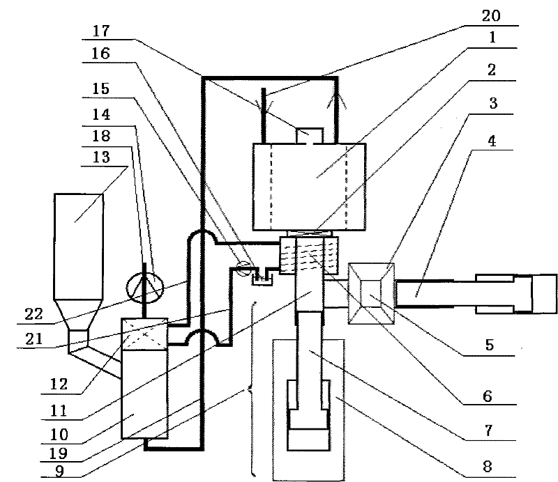
[0048] The straw raw material is stored in the hopper 3, relies on gravity, passes through the feeding port 5, and falls into the low-pressure hydraulic mechanism. The end of the piston of the low-pressure hydraulic mechanism forms a semi-cylindrical notch, and cooperates with the preforming section of the high-pressure hydraulic mechanism to compress the straw raw material into a cylindrical preforming raw material.

[0049] Straw raw materials should be compressed into shaped granules, and the ratio of the apparent density of shaped g...


PUM


Abstract

The invention discloses a double hydraulic heating straw compression molding process and double hydraulic heating straw compression molding equipment. The equipment comprises a low-pressure hydraulic mechanism, a high-pressure hydraulic mechanism, a squirrel-cage cooler and a heat-conducting oil furnace. The high-pressure hydraulic mechanism comprises a high-pressure hydraulic piston which is fixed on a reciprocating engine base, a pre-molding segment and a heating molding segment. The low-pressure hydraulic mechanism is vertically communicated with the pre-molding segment of the high-pressure hydraulic mechanism. A raw material is compressed by the low-pressure hydraulic mechanism to be formed into a pre-molded raw material, then the pre-molded raw material is processed at the heating molding segment of the high-pressure hydraulic mechanism to be formed into molded particles, and finally the molded particles enter the squirrel-cage cooler to be cooled. The heat-conducting oil furnaceuses the molded particles as a fuel to supply heat to the heating and compression processes and fully combusts aldehyde gases generated in the heating process. Compared with the conventional spiral compression molding machine, the equipment has the advantages of lower power consumption and smaller abrasion; compared with the conventional hydraulic compression molding machine, the equipment has the advantage of much higher unit output; and compared with the conventional electric heating compression molding machine, the equipment has the advantages of avoiding aldehyde pollution caused by the release of volatile matters, optimizing the energy source consumption structure and increasing economic benefits.

Description

technical field [0001] The invention relates to a compression molding machine, in particular to a straw compression molding machine. Background technique [0002] Fossil energy such as coal, oil and natural gas not only provides energy and power for the development of human society, but also causes great harm to the living environment of human beings, such as greenhouse effect, NOx emissions, SO 2 emissions and dust pollution. At the same time, human society is also facing the problem of fossil energy depletion. Therefore, seeking to develop new energy sources and realizing the sustainable development of society has been paid more and more attention by countries all over the world. Biomass energy, as a renewable clean energy, has a good development prospect. The National Academy of Sciences of the United States clearly stated in "Energy Transformation 1985-2010": "By 2010, the energy obtained from large-scale biomass conversion will be 20 times the total energy demand in ...

Claims


Application Information

Patent Timeline
Patent Type & Authority Patents(China)
IPC IPC(8): F23K1/00
Inventor 王启民张小辉关新
Owner SHENYANG INST OF ENG
Why Eureka
Try Eureka