
Millimeter wave generating device based on optic-fiber ring resonator and method thereof

A ring resonant cavity, millimeter wave technology, applied in electromagnetic transmitters, electromagnetic wave transmission systems, electrical components, etc., can solve the problems of high four-wave mixing threshold, low millimeter wave signal efficiency, system instability, etc. Quadruple frequency efficiency, compact structure, good compatibility

Inactive Publication Date: 2010-10-27
ZHEJIANG UNIV
View PDF2 Cites 19 Cited by
  • Summary
  • Abstract
  • Description
  • Claims
  • Application Information

AI Technical Summary

Problems solved by technology

This method requires a narrow linewidth laser source, and the system cost is too high
(2) Use the four-wave mixing effect of optical fiber or optical semiconductor amplifier to up-convert the reference microwave signal. The disadvantage of this method is that the threshold value of the four-wave mixing effect is very high, and changes in the external environment are likely to cause system instability.
(3) Using an external optical modulator to achieve frequency doubling and quadrupling of the reference microwave signal. This technology is widely used in today's ROF systems, but the disadvantage of this technology is that the system requires a high-power reference microwave signal. Inefficient generation of mmWave signals, introducing additional microwave amplifiers and the resulting unwanted noise

Method used


Image

  • Millimeter wave generating device based on optic-fiber ring resonator and method thereof
  • Millimeter wave generating device based on optic-fiber ring resonator and method thereof
  • Millimeter wave generating device based on optic-fiber ring resonator and method thereof

Examples


Embodiment Construction

[0015] The present invention will be further described below in conjunction with accompanying drawing:

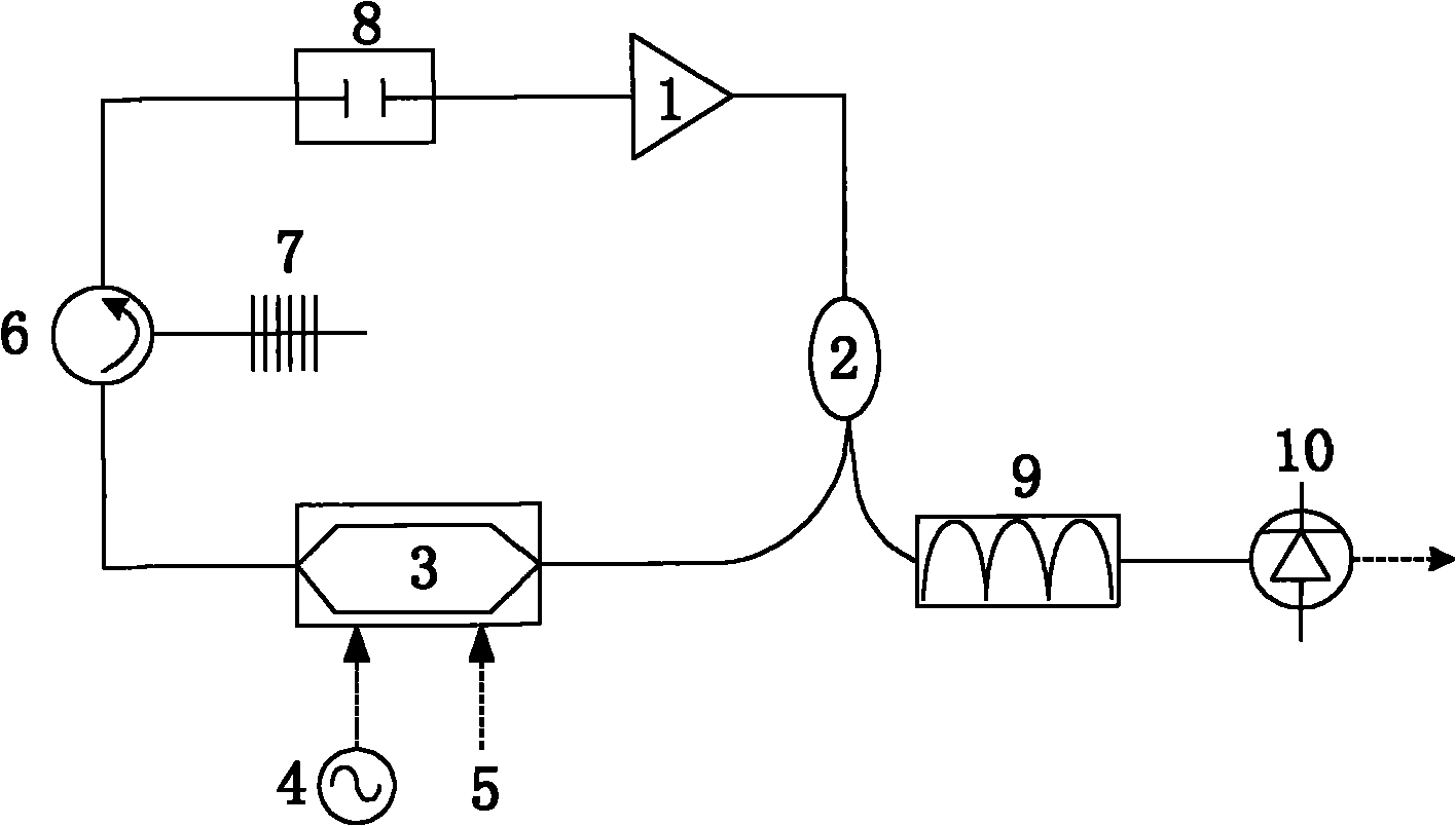
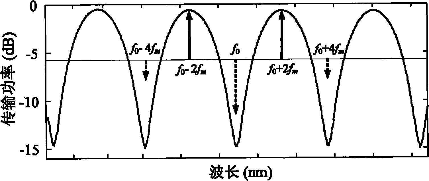
[0016] as attached figure 1 As shown, the millimeter-wave generating device based on the fiber ring resonator includes a semiconductor optical amplifier 1, a 1×2 polarization-maintaining fiber optical coupler 2, a Mach-Zehnder intensity modulator 3, a microwave source 4, a DC stabilized power supply 5, and a three-port Polarization-maintaining optical circulator 6, polarization-maintaining optical fiber grating 7, polarization-maintaining optical delay line 8, wavelength-tunable optical comb filter 9, high-speed photodetector 10; semiconductor optical amplifier 1 is connected with 1×2 polarization-maintaining optical coupler 2, 1 One of the output ports of the ×2 polarization-maintaining optical coupler 2 is sequentially connected to the first port of the Mach-Zehnder intensity modulator 3 and the three-port polarization-maintaining optical circulator 6, and the second port...


PUM


Abstract

The invention discloses a millimeter wave generating device based on an optic-fiber ring resonator and a method thereof. The optic-fiber ring resonator is formed by connecting a semiconductor optical amplifier, a 1*2 polarization maintaining coupler, a Mach-Zehnder intensity modulator, a three-port polarization maintaining circulator, a polarization maintaining fiber grating and a polarization maintaining optical delay line in sequence, the output of the optic-fiber ring resonator obtained through the other output end of the 1*2 polarization maintaining coupler is connected with a high-speed photoelectric detector through an optical comb filter with an adjustable wavelength, and when the Mach-Zehnder intensity modulator modulates a microwave source with the frequency being fm, and millimeter wave signals with the being 4fm are generated at the radio-frequency output end of the high-speed photoelectric detector through controlling the DC offset voltage of the Mach-Zehnder intensity modulator and the length of the fine-tuning polarization maintaining optical delay line. The invention has the advantages of high millimeter-wave efficiency, compact structure, stable operation, electromagnetic interference resistance and the like.

Description

technical field [0001] The invention relates to the fields of millimeter-wave optical fiber communication and millimeter-wave optical generation, in particular to a millimeter-wave generating device based on an optical fiber ring resonant cavity and a method thereof. Background technique [0002] Radio over fiber (ROF) is a communication technology that combines wireless communication and optical communication. The signal is loaded onto the optical carrier through subcarrier multiplexing technology, and the wireless signal is distributed from the central station to each base station (BS) through optical fiber links. , and then transmit the base station signal back to the central station (CS). With people's higher and higher requirements for data transmission rates, the bandwidth of wireless signals has been extended to the millimeter wave band, especially the 60GHz band. Due to the limitations of electronic bottlenecks, there are a series of disadvantages in generating and ...

Claims


Application Information

Patent Timeline
IPC IPC(8): H04B10/12H04B10/50H04B10/54H04B10/564
Inventor 杨波金晓峰章献民池灏郑史烈
Owner ZHEJIANG UNIV
Learn More