Rectangular etching ion gun

An ion gun and rectangular technology, applied in the field of rectangular etching ion guns, can solve the problems of inability to etch devices with large aspect ratios, shortened cathode filament life, poor ion beam uniformity, etc., and achieves lower temperature and faster etching speed. , The effect of ion beam uniformity

An ion gun and rectangular technology, applied in the field of rectangular etching ion guns, can solve the problems of inability to etch devices with large aspect ratios, shortened cathode filament life, poor ion beam uniformity, etc., and achieves lower temperature and faster etching speed. , The effect of ion beam uniformity

CN101908458AInactive Publication Date: 2010-12-08马利民

Image

  • Rectangular etching ion gun
  • Rectangular etching ion gun
  • Rectangular etching ion gun

Examples


Embodiment 1

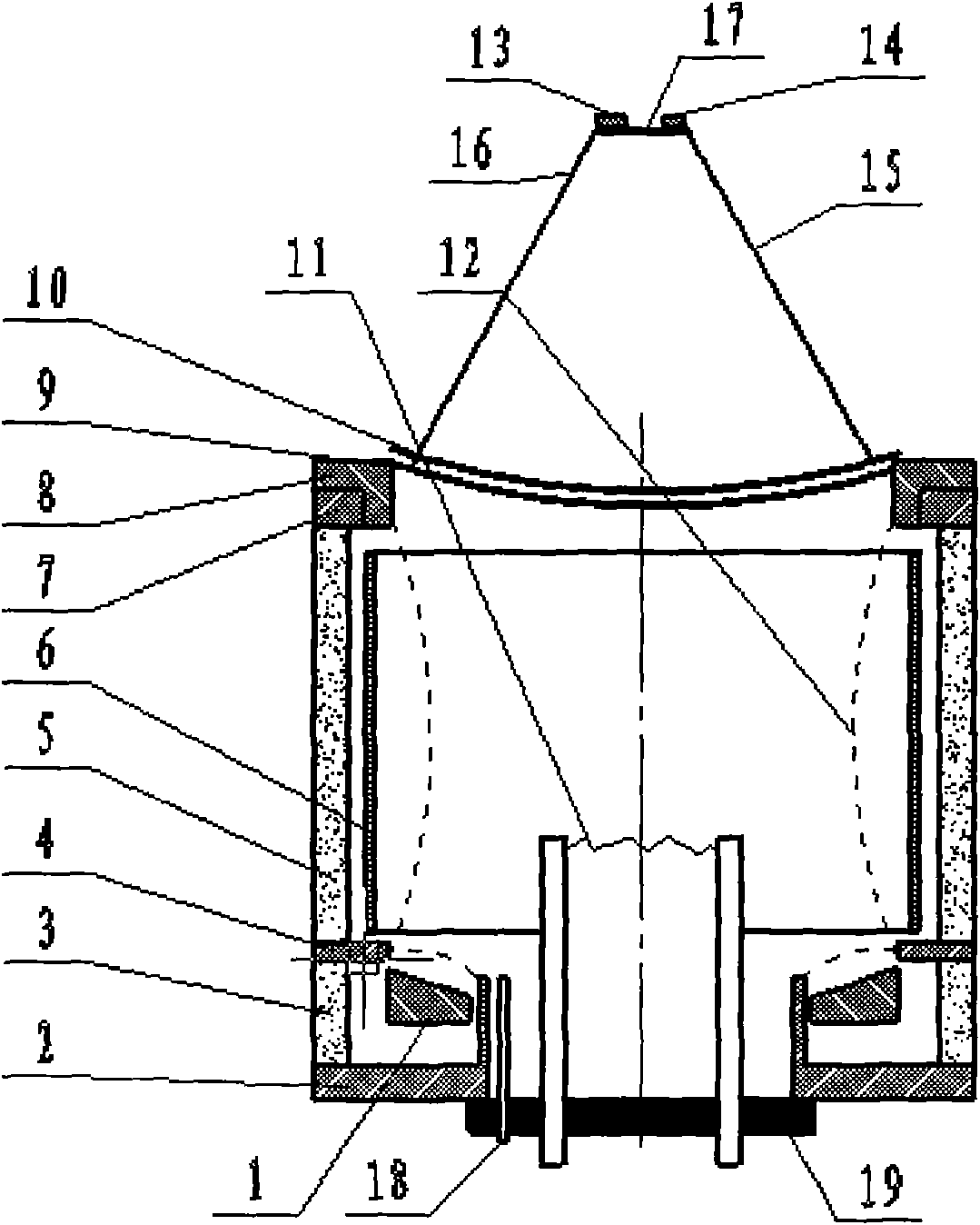
[0077] Such as figure 1 As shown, the first pole piece 2, the first magnet 3, the second pole piece 4, the second magnet 5, the third pole piece 7 and the fourth pole piece 8 in this embodiment constitute a rectangular shape. overall;

[0078] The first pole shoe 2 is an annular rectangular plate with a rectangular tube in the center of the upper surface, and the external dimensions of the annular rectangular plate are: 90mm (width)*150mm (length)*5mm (thickness), with a single side width of 25mm ; The size of the rectangular tube is: 40mm (width) * 110mm (length) * 20mm (height), the wall thickness of the rectangular tube is 2mm;

[0079] The second pole shoe 4 is a ring-shaped rectangular plate, and its external dimensions are: 90mm (width)*150 (length)*2mm (thickness), with a single side width of 10mm

[0080] The third pole shoe 7 is a ring-shaped rectangular plate, and its external dimensions are: 90mm (width)*150mm (length)*5mm (thickness), and the width of one side i...


PUM


Abstract

The invention relates to a rectangular etching ion gun which comprises a first pole shoe, a second pole shoe, a third pole shoe, a fourth pole shoe, a first magnet, a second magnet, a fourth pole shoe, a rectangular annular upper anode, a rectangular annular lower anode, a rectangular conical surface, an arc plate-shaped screen grid, an arc plate-shaped accelerating grid, a base, a cathode lamp, a lamp filament and an inflating pipe, wherein the first pole shoe, the second pole shoe, the third pole shoe and the fourth pole shoe are coaxially arranged from bottom to top; the first magnet is positioned between the end surfaces of the first pole shoe and the second pole shoe; the second magnet is positioned between the end surfaces of the second pole shoe and the third pole shoe; the fourth pole shoe is positioned on the end surface of the third pole shoe; the rectangular annular upper anode is positioned in the second magnet; the rectangular annular lower anode is positioned between the first magnet and a rectangular pipe; the rectangular conical surface with high outside and low inside is arranged on the upper end surface of the rectangular annular lower anode; the arc plate-shaped screen grid is overlapped at the upper end surface of the fourth pole shoe; the arc plate-shaped accelerating grid is suspended on the screen grid; the base is arranged in the center of the lower surface of the first pole shoe and covers an inner hole of the rectangular pipe; the cathode lamp is fixed on the base and positioned in the rectangular pipe; the lamp filament is positioned in a rectangular ring of the rectangular annular upper anode; and the inflating pipe is positioned between the rectangular pipe and the cathode lamp after penetrating through the base and communicated with an argon source. The invention has the advantages of less etching gas dosage, small size, low power consumption, even ion beam, and the like.

Description

technical field [0001] The invention belongs to ion gun equipment for etching quartz crystal, in particular to a rectangular etching ion gun. technical background: [0002] With the development of information technology, electronic components are becoming more and more miniaturized, and quartz crystals, as the key components (chips) of clocks, are also getting smaller and smaller. The quartz crystal used for the clock must be adjusted by frequency (that is, the adjustment of the thickness of the silver-plated layer of the quartz crystal) to ensure the accuracy of the clock. Generally, there are two ways to control the frequency of quartz crystals. One is to control the thickness of the silver layer of quartz crystals by vacuum evaporating the silver layer on the quartz crystals (quartz crystal frequency control). This method is suitable for large-sized quartz crystals. The binding force between the plated silver layer and the quartz crystal is tensile stress, which is relat...

Claims


Application Information

Patent Timeline
08 Dec 2010
Publication
CN101908458A
IPC
H01J37/08; C30B33/08
Inventors
马利民