Carborundum fingered schottky contact nuclear battery

A Schottky contact and nuclear battery technology, which is applied in the field of microelectronics, can solve the problems of reduced energy conversion efficiency, low energy conversion efficiency, and large energy loss of incident particles, and achieves improved energy conversion efficiency, improved energy conversion efficiency, and process simple effect

Active Publication Date: 2010-12-15
陕西半导体先导技术中心有限公司
View PDF3 Cites 10 Cited by
  • Summary
  • Abstract
  • Description
  • Claims
  • Application Information

AI Technical Summary

Problems solved by technology

In this PN junction structure, in order to prevent the ohmic contact electrode from blocking incident particles, the ohmic electrode must be overloaded in one corner of the device, but this will cause the irradiated carriers far away from the ohmic electrode to be recombined during the transport process, and Incident particles must pass through the SiO at the surface 2 The passivation layer and part of the P-type layer cause energy loss and reduce energy conversion efficiency
[0007] The nuclear battery disclosed in Chinese patent CN 101325093A adopts a Schottky junction structure, which avoids the difficulty in realizing the above-mentioned PN junction technology, but the Schottky contact layer of the Schottky nodule battery covers the entire battery area, as shown in Figure 8 As shown, since the incident particles reach the surface of the device, they will be blocked by the Schottky contact layer, only part of the particles can enter the device, and the particles entering the depletion region will contribute to the output power of the battery. Therefore, this The energy loss of the incident particles in the nuclear battery structure is large, and the energy conversion efficiency is low

Method used


Image

  • Carborundum fingered schottky contact nuclear battery
  • Carborundum fingered schottky contact nuclear battery
  • Carborundum fingered schottky contact nuclear battery

Examples


Embodiment 1

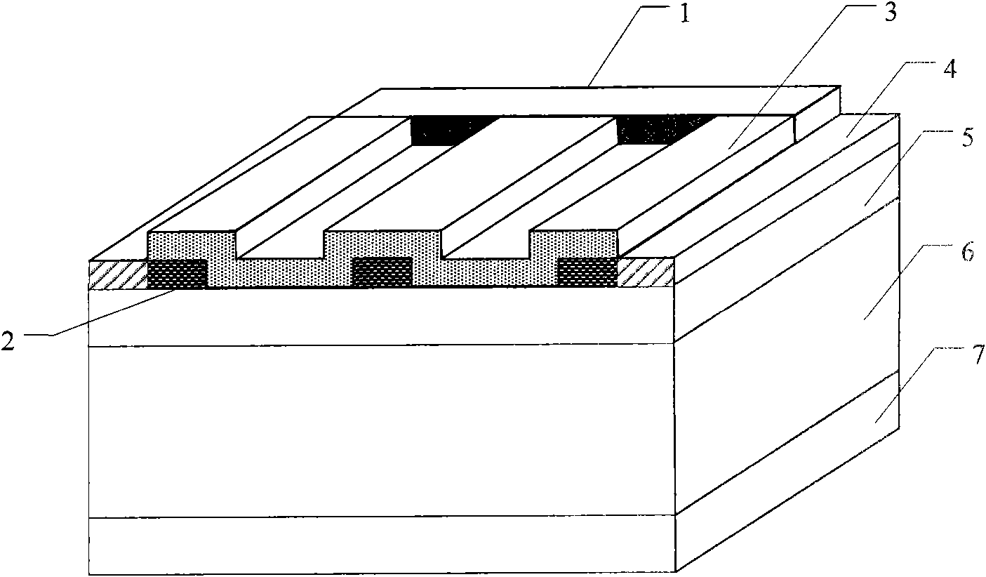
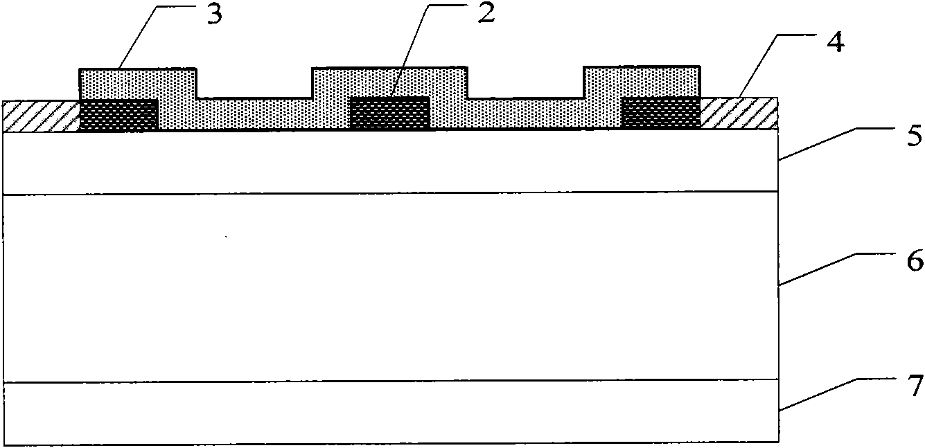
[0037] Step 1, epitaxial low-doped n-type epitaxial layer on SiC highly-doped n-type substrate, such as Image 6 a.

[0038] The selected doping concentration is 5 × 10 18 cm -3 The SiC highly doped n-type SiC substrate is used as the substrate 6. After cleaning, the epitaxial surface is grown with a thickness of about 3 μm by a low-pressure hot-wall chemical vapor deposition method. The doping concentration is 5 × 10 15 cm -3 The 4H-SiC low-doped epitaxial layer 5 has an epitaxial temperature of 1570° C., a pressure of 100 mbar, the reaction gases are silane and propane, and the carrier gas is pure hydrogen.

[0039] Step 2, Form SiO on the epitaxial layer 2 passivation layers such as Image 6 b.

[0040] The epitaxial substrate samples were subjected to dry oxygen oxidation for two hours at a temperature of 1100 ± 50 °C to form SiO 2 passivation layer.

[0041] In step 3, an ohmic contact is formed on the backside of the substrate, such as Image 6 c.

[0042] (3.1...

Embodiment 2

[0053] The first step is to epitaxy a low-doped n-type epitaxial layer on a SiC highly-doped n-type substrate.

[0054] The doping concentration is selected as 1×10 18 cm -3 The SiC highly doped n-type SiC substrate is used as the substrate 6. After cleaning, the epitaxial surface is grown with a thickness of about 3 μm by a low-pressure hot-wall chemical vapor deposition method. The doping concentration is 3 × 10 15 cm -3 The 4H-SiC low-doped epitaxial layer 5 has an epitaxial temperature of 1570° C., a pressure of 100 mbar, the reaction gases are silane and propane, and the carrier gas is pure hydrogen.

[0055] The second step is to form SiO on the epitaxial layer 2 passivation layer.

[0056] The epitaxial substrate samples were subjected to dry oxygen oxidation for two hours at a temperature of 1100 ± 50 °C to form SiO 2 passivation layer.

[0057] In the third step, an ohmic contact is formed on the backside of the substrate.

[0058] (3.1) etching a SiC layer wit...

Embodiment 3

[0069] Step A, epitaxial low-doped n-type epitaxial layer on SiC highly-doped n-type substrate.

[0070] The selected doping concentration is 5 × 10 17 cm -3 The SiC highly doped n-type SiC substrate is used as the substrate 6. After cleaning, the epitaxial surface is grown with a thickness of about 3 μm by a low-pressure hot-wall chemical vapor deposition method. The doping concentration is 1×10 15 cm -3 The 4H-SiC low-doped epitaxial layer 5 has an epitaxial temperature of 1570° C., a pressure of 100 mbar, the reaction gases are silane and propane, and the carrier gas is pure hydrogen.

[0071] Step B, forming SiO on the epitaxial layer 2 passivation layer.

[0072] The epitaxial samples were subjected to dry oxygen oxidation for two hours at a temperature of 1100 ± 50 °C to form SiO 2 passivation layer.

[0073] In step C, an ohmic contact is formed on the backside of the substrate.

[0074] (C1) etching a SiC layer with a thickness of 0.5 μm on the backside of the s...


PUM


Abstract

The invention discloses a carborundum based fingered Schottky contact nuclear battery and a fabricating method thereof, mainly solving the problems of difficult fabrication process of a carborundum pn nodule battery and low efficiency of a Schottky nodule battery in the prior art. The carborundum based fingered Schottky contact nuclear battery sequentially comprises a bonding layer (1), a radioactive isotope source layer (3), a fingered semitransparent Schottky contact layer (2), an n type SiC epitaxial layer (5) with doping concentration of 5*1015-5*1015cm<-3>, an n type SiC substrate (6) with doping concentration of 5*1017-5*1018cm<-3> and an ohmic contact electrode (7), wherein an SiO2 passivation layer (4) surrounds the radioactive isotope source layer. The fingered semitransparent Schottky contact layer (2) comprises one horizontal finger strip and a plurality of vertical finger strips, wherein all the vertical finger strips are positioned at one side of the horizontal finger strip, and the radioactive isotope source layer (3) is positioned on the epitaxial layer (5) between the vertical finger strips and the horizontal finger strip. The invention has the advantages of little energy loss and high energy conversion efficiency, and can be used as an on-chip power supply of an MEMS (Micro-electromechanical System), a cardiac pacemaker power supply and a mobile phone standby power supply.

Description

technical field [0001] The invention belongs to the field of microelectronics, and in particular relates to a finger-shaped Schottky contact nuclear battery based on silicon carbide, which can be used to directly convert nuclear energy emitted by isotopes into electrical energy. technical background [0002] Elgin-Kidde first used the β-Voltaic Effect in power supply in 1957, and successfully produced the first isotope microbattery (β-Voltaic Battery). Since 1989, materials such as GaN, GaP, AlGaAs, and polysilicon have been successively used as materials for β-Voltaic cells. With the advancement of the preparation and process technology of the wide-bandgap semiconductor material SiC, since 2006, there have been international reports on SiC-based isotope batteries. [0003] The document "APPLIED PHYSICS LETTERS 88, 064101 (2006) "Demonstration of atadiation resistant, hight efficiency SiC betavoltaic"" introduced C.J.Eiting, V.Krishnamoorthy, and S.Rodgers, T.George of Qyne...

Claims


Application Information

Patent Timeline
Patent Type & Authority Applications(China)
IPC IPC(8): G21H1/00
Inventor 郭辉石彦强张玉明韩超陈丰平侯学智
Owner 陕西半导体先导技术中心有限公司
Why Eureka
Try Eureka