Equal-current synthetic high-power constant current power supply circuit

A constant current power supply, high power technology, applied in the direction of circuits, electrical components, laser components, etc., can solve problems such as output current imbalance, power tube damage, drive stability, poor reliability and safety, and improve reliability , enhance the effect of stability

Inactive Publication Date: 2010-12-15
JILIN UNIV
View PDF2 Cites 21 Cited by
  • Summary
  • Abstract
  • Description
  • Claims
  • Application Information

AI Technical Summary

Problems solved by technology

[0005] The purpose of the present invention is to provide a current equalization synthetic high-power constant current power supply circuit, which can effectively overcome the disadvantage of unbalanced output current of each tube when multiple tubes are connected in parallel, and solve the heat accumulation of power tubes in the prior art. Causes damage to the power tube, making the drive unable to work stably, and poor drive stability, reliability, and safety

Method used


Image

  • Equal-current synthetic high-power constant current power supply circuit
  • Equal-current synthetic high-power constant current power supply circuit
  • Equal-current synthetic high-power constant current power supply circuit

Examples


Embodiment 1

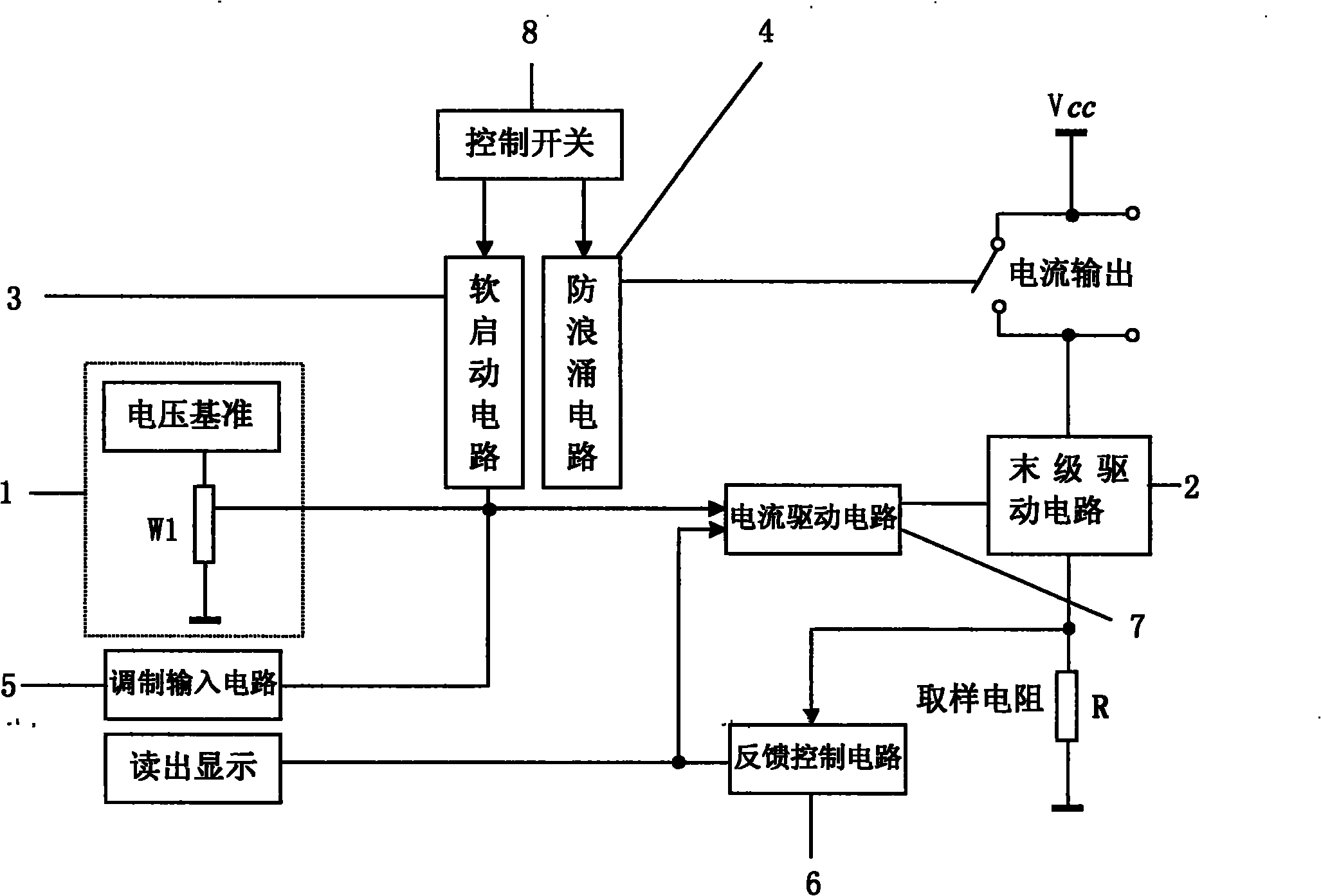
[0023] Such as figure 1 As shown, the current equalizing synthetic high-power constant-current power supply circuit of the present invention includes a voltage reference circuit 1, a final drive circuit 2, a soft-start circuit 3, an anti-surge circuit 4, a modulation input circuit 5, a feedback control circuit 6, and a current drive circuit. Circuit 7 and control switch 8; voltage reference circuit 1 is composed of a voltage reference LM336-2.5 and a 9.1 kohm resistor, which provides accurate and stable reference voltage for the circuit to control the output current and preset limit current. Potentiometer W1 is used to adjust the output current. The final drive circuit 2 outputs a set current, and adopts a method of connecting multiple MOS transistors in parallel, and the emitter of each MOS transistor is connected in series with a current sharing resistor. The current drive circuit 7 converts the control voltage into an output current. The feedback control circuit 6 realize...

Embodiment 2

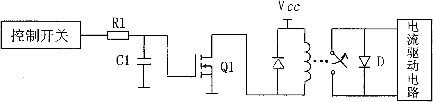
[0025] Such as figure 2 As shown, the anti-surge circuit 4 includes an RC charging circuit composed of a resistor R1 and a capacitor C1, an N-channel enhanced field effect transistor Q1, and a normally closed solid state relay. The gate of the field effect transistor Q1 is connected to the resistor R1 and the capacitor C1, the other end of the capacitor C1 is grounded, the drain of the field effect transistor Q1 is connected to the relay, and the source of the field effect transistor Q1 is grounded. The type of field effect transistor Q1 may be 2sk1458.

[0026] The working principle of the circuit is: the anode and cathode of the laser diode LD are connected in parallel with the two normally closed ends of the relay, so the cathode and anode of the laser diode LD are short-circuited and protected. When the driver is turned on, if the control switch is not turned on, the laser diode LD is still short-circuited. Only after the control switch 8 is turned on, the normally close...

Embodiment 3

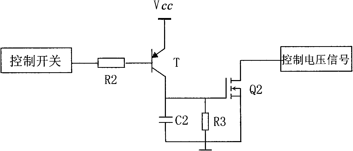
[0028] Such as image 3 As shown, the soft start circuit 3 includes a PNP transistor T, an RC discharge circuit composed of a resistor R3 and a capacitor C2, and an N-channel enhanced field effect transistor Q2. The gate of the field effect transistor Q2 is connected to the resistor R3 and the capacitor C2, and the other end of the resistor R3 and the capacitor C2 is grounded; the drain of the field effect transistor Q2 is connected to the control signal, and the source of the field effect transistor Q2 is connected to the ground; the base of the triode T The electrode is connected to the control switch 8 through the resistor R2, and the emitter of the triode T is connected to the working power supply V CC , the collector of the transistor T is connected to the gate of Q2.

[0029] Among them, the model of the triode T can be selected as 9012, and the model of the field effect transistor Q2 can be selected as 2sk1458.

[0030]The function of the soft start circuit is: after ...


PUM


Abstract

The invention relates to an equal-current synthetic high-power constant current power supply circuit, which belongs to the fields of electronic industry and optical communication. The circuit comprises a voltage reference circuit, a final driving circuit, a soft-start circuit, an anti-surge circuit, a modulation input circuit, a feedback control circuit, a current driving circuit and a control switch; the final driving circuit comprises high-power semiconductor devices and equal-current resistors which are connected in parallel, the equal-current resistors are respectively and correspondingly connected in series with drains of the high-power semiconductor devices, output current generated by the high-power semiconductor devices is merged and then flows through a sampling resistor; and the drains of the high-power semiconductor devices are respectively connected with a cathode of a semiconductor laser, and sources of the high-power semiconductor devices are connected with the sampling resistor. The circuit has the advantages of greatly enhancing the stability of the current output by a high-power semiconductor laser driver, enabling the current that flows through each MOS tube to be basically equal by adopting the equal-current technology, and greatly enhancing the reliability of a power supply in a high-load working state.

Description

technical field [0001] The invention relates to the fields of electronic industry and optical communication, in particular to a current equalizing and synthesizing high-power constant-current power supply circuit. Background technique [0002] High-power semiconductor lasers are necessary pump light sources for solid-state lasers in industrial production, military defense and other industries. They are widely used in laser ranging, nuclear explosion simulation, lidar transmission, material processing, microprocessing, heat treatment, marking positioning, etc. In addition, high-power lasers are also widely used in medical fields such as surgical treatment of tumors, skin treatment, dental treatment, photoanalgesia, photoacupuncture, and optical tomography (OCT). [0003] What drives the high-power semiconductor laser is a dedicated drive power supply with special functions. High-power semiconductor lasers are expensive. They are devices with high power density and extremely ...

Claims


Application Information

Patent Timeline
Patent Type & Authority Applications(China)
IPC IPC(8): H01S5/042
Inventor 单江东田小建汝玉星吴戈高博
Owner JILIN UNIV
Why Eureka
Try Eureka