LED heat radiating device
A heat dissipation device and LED substrate technology, applied in the direction of electrical components, circuits, semiconductor devices, etc., can solve the problems of large volume, poor heat dissipation effect, etc., achieve the effects of fast thermal response, reduce welding work, and avoid damage
- Summary
- Abstract
- Description
- Claims
- Application Information
AI Technical Summary
Problems solved by technology
Method used
Image
Examples
Embodiment 1
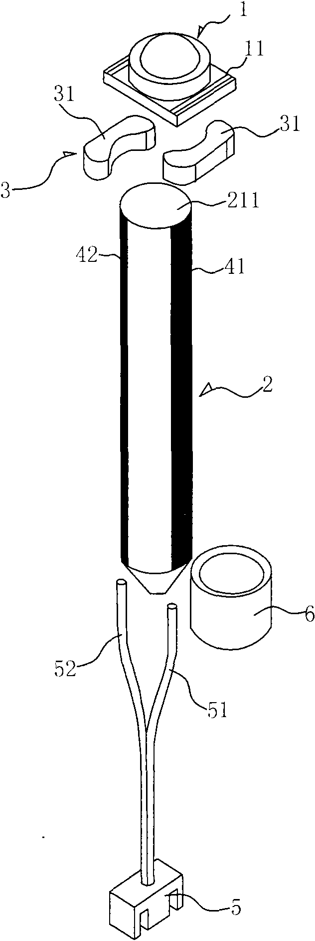
[0032] See figure 1 , 2 , this embodiment includes: an LED 1 and a heat conduction heat pipe 2 connected to the LED substrate 11 . The LED 1 includes: an LED chip and an LED substrate 11 for carrying the LED chip. In order to improve the heat dissipation efficiency, the LED substrate 11 in this embodiment adopts low temperature co-fired multilayer ceramics, which can effectively and quickly dissipate the heat generated by the LED chips.
[0033] The heat conduction heat pipe 2 includes: a heat pipe body 21 and an insulating layer 22 covering the heat pipe body 21 , wherein the heat pipe body 21 is in the form of a cylinder, and the surface of the insulating layer 22 is coated with conductive lines. In order to improve heat conduction efficiency, the heat pipe main body 21 in this embodiment is made of copper pipe, and the heat pipe main body 21 is fixed on the bottom surface of the LED substrate 11 by bonding. Its end surface 211 in contact with the LED substrate 11 is a pl...
Embodiment 2
[0043] See image 3 , 4 As shown, this embodiment is similar to Embodiment 1, the difference is that the positive and negative poles of the LED on the LED substrate 11 use a conductive member 3 that is a contact piece 32 made of copper, through which the contact piece 32 is connected with the silver paste circuit The formed power lines 41, 42 are connected. Specifically, the conductive member 3 includes: a contact piece 32 and an insulating seat 33 for fixing the contact piece 32, wherein the insulating seat 33 is fixed on the end of the heat pipe main body 21, the contact piece 32 is fixed on the insulating seat 33, and Each contact piece 32 communicates with the power supply lines 41 , 42 at corresponding positions and the positive and negative contacts of the LED 1 .
[0044] Since the copper contact piece 32 is difficult to be directly fixed on the heat pipe main body 21, an insulating seat 33 is used to fix the contact piece 32 in this embodiment, and the insulating sea...
Embodiment 3
[0046] See Figure 5 , 6 As shown, this embodiment is similar to Embodiment 1, the difference is that: the tail end of the heat pipe body 21 (that is, the condensation end of the heat conduction heat pipe 2) is welded or riveted with fins 23, through which the fins 23 increase the contact with the environment. The heat dissipation area for air heat exchange increases the heat dissipation effect. The materials used as fins are still mainly copper (such as Cu1100) and aluminum (such as AL1100), as well as the recent aluminum-based ceramic composite material (also known as AMC composite material). According to the processing methods, there are stamping, extrusion, casting, welding, folding, forging, cutting, machining and so on. The structure can be designed in different shapes according to the product, and the fins 23 need to optimize the fin pitch, fin thickness, and fin outer diameter according to the LED power and carry out check calculation.
PUM
 Abstract
Description
Claims
Application Information
 - R&D
- Intellectual Property
- Life Sciences
- Materials
- Tech Scout
- Unparalleled Data Quality
- Higher Quality Content
- 60% Fewer Hallucinations
Browse by: Latest US Patents, China's latest patents, Technical Efficacy Thesaurus, Application Domain, Technology Topic, Popular Technical Reports.
© 2025 PatSnap. All rights reserved.Legal|Privacy policy|Modern Slavery Act Transparency Statement|Sitemap|About US| Contact US: help@patsnap.com


