
Liquid crystal machine-readable anti-false element

A technology of anti-counterfeiting components and liquid crystals, applied in optics, printing, instruments, etc., can solve problems such as insufficient anti-counterfeiting measures to ensure anti-counterfeiting effects, lowering the anti-counterfeiting level of securities and anti-counterfeiting marks, and public confusion

Inactive Publication Date: 2013-04-10
SECURITY PRINTING INST OF PEOPLES BANK OF CHINA +1
View PDF9 Cites 0 Cited by
  • Summary
  • Abstract
  • Description
  • Claims
  • Application Information

AI Technical Summary

Problems solved by technology

However, 1000 to 2500nm includes a large range, and there are currently pigments on the market that have strong absorption of electromagnetic waves from 1000 to 2500nm and have no obvious absorption of electromagnetic waves at 800nm. Marked anti-counterfeiting level
[0008] To sum up, anti-counterfeiting using the angle-changing optical effect of optical elements or the polarization properties of liquid crystal materials has been widely used, and has played a very good role in anti-counterfeiting for a long time in the past. However, optically variable pigments (OVP) and liquid crystal pigments with polarizing or angle-changing properties for making such optical anti-counterfeiting elements can be easily obtained on the market, and many optical anti-counterfeiting elements have the same or similar angle-dependent The color-changing effect is easy to confuse the public, and pigments with infrared absorption alone are easily available in the market, so a single anti-counterfeiting measure is not enough to ensure that the anti-counterfeiting effect is foolproof

Method used

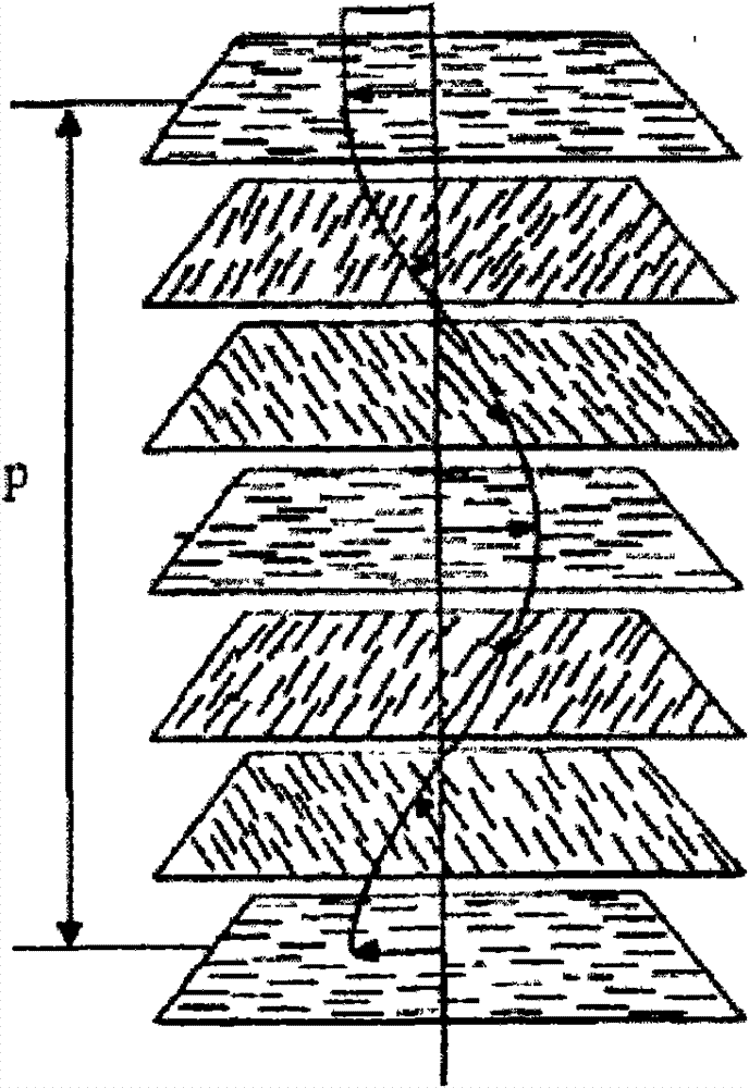
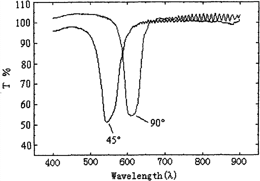
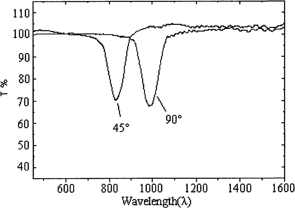

Image

  • Liquid crystal machine-readable anti-false element
  • Liquid crystal machine-readable anti-false element
  • Liquid crystal machine-readable anti-false element

Examples


Embodiment 1

[0052] Three kinds of nematic liquid crystal prepolymer materials described in US6806930 (its structural formulas are shown in formulas I-1, I-2 and I-3 respectively), chiral substance ST31L (its structural formulas are shown in formula II) , IRGACURE photoinitiator of Ciba-Geigy company, anisole, cyclopentanone are mixed mutually, make cholesteric liquid crystal solution (mass percentage range of various materials is as shown in Table 1), wherein chiral substance accounts for solid component 3.5wt.% of the total amount;

[0053] Coat the above-mentioned cholesteric liquid crystal solution on the transparent PET film (substrate layer) 1 with a wire rod, dry and remove the solvent, and cure the dried coating with ultraviolet light under a nitrogen atmosphere to form a layer of cholesteric liquid crystal. Layer 211;

[0054] Coat the above-mentioned cholesteric liquid crystal solution again in the part of this cholesteric liquid crystal layer, dry and solidify the coating to fo...

Embodiment 2

[0067] Three kinds of nematic liquid crystal prepolymer materials used in Example 1, the chiral substance described in US2002076510 (its structural formula is shown in formula III), IRGACURE photoinitiator of Ciba-Geigy company, anisole, cyclopentyl Mix ketones with each other to make a cholesteric liquid crystal solution, change the concentration of the chiral substance so that it is in the lower part of the content range shown in Table 1, and prepare cholesteric liquid crystal solution 1 and cholesteric liquid crystal solution 2 ;

[0068] These two cholesteric liquid crystal solutions 1 and 2 are overprinted on the BOPP substrate (substrate layer) 1 by gravure, dried, and UV cured to form a cholesteric liquid crystal layer 2, forming regions 21 and 22;

[0069] On the other side of the BOPP substrate, hard magnetic ink and soft magnetic ink are overprinted, and after drying, hard magnetic regions (HM) 321 and soft magnetic regions (SM) 322 are formed respectively, forming s...

Embodiment 3

[0074] Three kinds of nematic liquid crystal prepolymer materials in Example 1, chiral substances provided by US6569356 (its structural formula is shown in formula IV, change the concentration of chiral substances in the content range shown in Table 1 for comparison Low part), IRGACURE photoinitiator of Ciba-Geigy company, methyl ethyl ketone, cyclopentanone are mixed mutually, are mixed with cholesteric liquid crystal solution 3 and 4;

[0075] The cholesteric liquid crystal solution 3 and 4 are overprinted on the PET substrate (substrate layer) 1 by gravure, dried, and UV cured to form the cholesteric liquid crystal layer, forming regions 31, 32 and 33, wherein the region 31 is The monolayer region formed by the cholesteric liquid crystal solution 3, the region 33 is the monolayer region formed by the cholesteric liquid crystal solution 4, and the region 32 is an overlapping region formed by two kinds of cholesteric liquid crystal solutions 3 and 4;

[0076] On the same side...


PUM

PropertyMeasurementUnit
full width at half maximumaaaaaaaaaa

Abstract

The invention relates to a liquid crystal machine-readable anti-false element which is provided with at least two regions made of cholesteric liquid crystal materials, wherein the central wavelengths of reflected lights at the same detection angle in the two regions compose first coded information, and the first coded information changes with the detection angle. The first coded information can be detected by an instrument and can avoid unauthorized reproduction, thereby eliminating the possibility of being faked. The liquid crystal machine-readable anti-false element realizes the combinationof second-grade anti-false features and third-grade machine-readable anti-false features, and can avoid the problem that the anti-false effect of the anti-false element can not be ensured by a singleanti-false measure as far as possible. At the same time, based on the anti-false features, the liquid crystal machine-readable anti-false element can also be combined with first-grade light-variable anti-false features based on angle-dependent color variation and other machine-readable and identifiable second-grade anti-false features of infrared, magnetism, ultraviolet and the like. The invention also provides economic goods provided with the liquid crystal machine-readable anti-false element.

Description

technical field [0001] The invention relates to a liquid crystal machine-readable anti-counterfeit element for protecting valuable items, in particular to a liquid crystal machine-readable anti-counterfeit element whose encoded information is composed of central wavelengths of reflected light in different regions. Background technique [0002] With the development of modern reproduction technology, counterfeiting crimes against various brand-name commodities, financial instruments and securities are becoming more and more rampant. By the way, some counterfeit securities have even reached the point where it is difficult to distinguish the real from the fake for the public, causing unnecessary confusion. The sophistication and extensiveness of counterfeiting technology have put forward higher requirements for anti-counterfeiting technology. [0003] At present, a variety of anti-counterfeiting methods have been developed and adopted in the field of anti-counterfeiting technol...

Claims


Application Information

Patent Timeline
Patent Type & Authority Patents(China)
IPC IPC(8): G02F1/137B42D15/00B41M3/14
Inventor 柯光明周基炜王斌刘卫东黄小义陈海波邓德斌
Owner SECURITY PRINTING INST OF PEOPLES BANK OF CHINA
Learn More