Gas supercharger

A gas booster and booster chamber technology, which is applied to fluid pressure converters, mechanical equipment, etc., can solve the problems of ineffective utilization of gas pressure, low energy utilization, large volume, etc., and achieves simple structure, wide application, smooth motion effect

Inactive Publication Date: 2011-02-02
王强
View PDF0 Cites 3 Cited by
  • Summary
  • Abstract
  • Description
  • Claims
  • Application Information

AI Technical Summary

Problems solved by technology

[0002] The gas pressurization device in the prior art mainly realizes the gas pressurization by means of pure mechanical compression in a sealable container. The vacuum in the container is achieved by purely mechanical compression. The conical screw type and the conical helical blade type realize the pressurization by rotating and generating vortex. These types of pressurization methods have a considerable amount of energy It is used for the friction between gas and machinery, machinery and machinery, gas and gas, resulting in low energy utilization rate and the inability to effectively use the pressure of the gas itself. Most booster devices are equipped with reciprocating parts, with complex structures and large volumes But the displacement is small

Method used


Image

  • Gas supercharger
  • Gas supercharger
  • Gas supercharger

Examples


Embodiment 1

[0024] Embodiment 1: for separating mixed gas

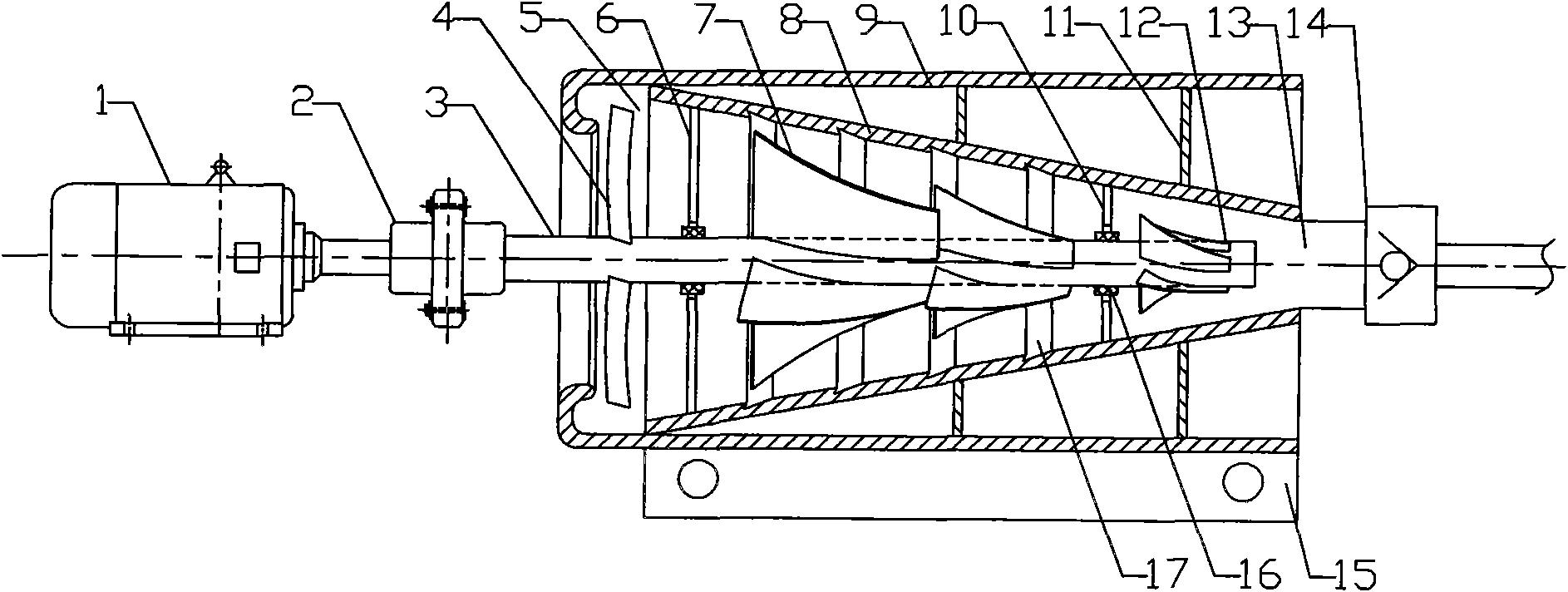
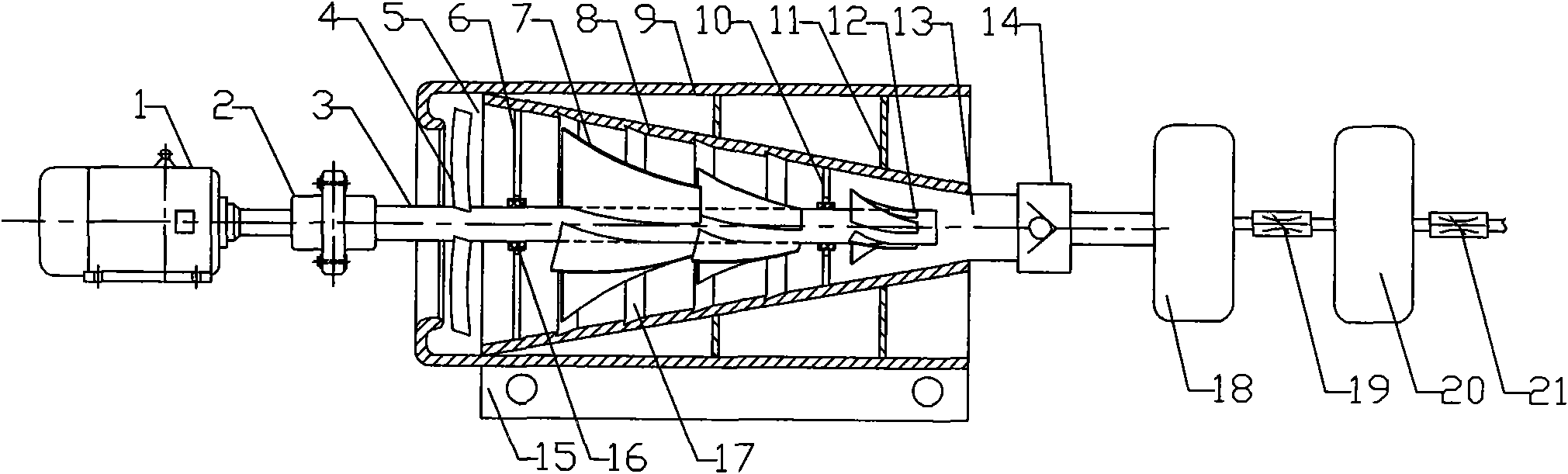
[0025] The power machine 1 drives the power transmission shaft 3 to rotate through the power connection device 2, and the gas on the power transmission shaft 3 is introduced into the paddle device 4, the semi-trapezoidal paddle device 7, and the gas export paddle device 12 rotates synchronously with the power transmission shaft 3. The gas is introduced into the paddle device 4 to introduce the gas into the conical plenum housing 8 through the gas inlet 5, and the gas introduction amount can be adjusted by adjusting the angle and cross-sectional area of ​​the blades. The left end of the cylindrical outer support housing 9 The U-shaped groove forms an annular recirculation chamber around the gas inlet paddle device 4 to prevent the outward diffusion of a small amount of introduced gas and improve energy utilization. The semi-trapezoidal paddle device 7 rotates while exerting force on the gas , so the gas at the large opening end of...

Embodiment 2

[0026] Example 2: Liquefaction system for corrosive gases

[0027] Process the working contact surface of the parts of the present invention by a simple method to make it a corrosion-resistant gas booster, and use the pressurization step of the embodiment of the invention 1 to diethyl ether ((C 2 h 5 ) 2 O), hydrogen sulfide (H 2 S), Chlorine (Cl 2 ) or nitrogen dioxide (NO 2 ) and other flammable and explosive toxic gases are pressurized, then liquefied into liquids, sealed and stored at low temperature, and the liquefaction method is used to compress the corrosive gases for storage and transportation in industrial applications, or use this method to recycle or effectively Treatment of waste gas that pollutes the atmosphere from industrial production.

Embodiment 3

[0028] Embodiment 3: for temperature regulation system

[0029] Also use the present invention to also ammonia (CH 3 ) is pressurized to convert it into liquid ammonia for easy storage and transportation; while ammonia gas (CH 3 ) The liquefaction or gasification will absorb and generate a lot of heat, so the temperature can be adjusted by constantly adjusting its pressure, changing its state of existence, and making it absorb or release a lot of heat.

[0030] In addition, the present invention can also be widely used in the fields of power generation systems, generator systems, liquid-gas mixing systems, gas delivery systems, vacuum systems, etc.; or add a sealable flange outside the cylindrical outer support shell 9, It can effectively reduce energy consumption, reduce production cycle and improve production efficiency when used in fields that require sealing production.


PUM


Abstract

The invention discloses a gas supercharger, which belongs to the field of gas supercharging devices. The gas supercharger of the invention can widely be used in gas supercharging and industrial waste-gas treatments in chemical industry, and can be available for the fields such as generating systems, liquid-gas mixing systems, gas delivery system, vacuum systems and the like. The gas supercharger is characterized in that the inner wall of a tapered supercharging-chamber shell (8) is provided with a plurality of backflow slots (17), and the section of each backflow slot is v-shaped; the left end of a power transmission shaft (3) arranged in supercharging-chamber shell (8) is provided with a half-trapezoid blade device (7), and the right end of the power transmission shaft (3) is provided with a gas-lead out blade device (12); a gas-outlet transmission shaft bracket (10) is arranged between the half-trapezoid blade device (7) and the gas-derived blade device (12); the left part of the half-trapezoid blade device (7) is provided with a gas-inlet transmission shaft bracket (6) and a gas-lead out blade device (4); and a gas outlet (13) of the tapered supercharging-chamber shell (8) is provided with a one-way valve (14). The invention has the advantages of no reciprocation components, simple structure, high energy utilization, large discharge, and the like.

Description

technical field [0001] A gas supercharger belongs to the field of gas supercharging devices, and in particular relates to a gas supercharger. Power generation system, generator system, liquid-gas mixing system, gas delivery system, vacuum system and other fields. Background technique [0002] The gas pressurization device in the prior art mainly realizes the gas pressurization by means of pure mechanical compression in a sealable container. The vacuum in the container is achieved by purely mechanical compression. The conical screw type and the conical helical blade type realize the pressurization by rotating and generating vortex. These types of pressurization methods have a considerable amount of energy It is used for the friction between gas and machinery, machinery and machinery, gas and gas, resulting in low energy utilization rate and the inability to effectively use the pressure of the gas itself. Most booster devices are equipped with reciprocating parts, with comple...

Claims


Application Information

Patent Timeline
Patent Type & Authority Applications(China)
IPC IPC(8): F15B3/00
Inventor 王强
Owner 王强
Why Eureka
Try Eureka