
Dynamic micro-electrolysis waste water treatment device and water treatment method thereof

A technology for dynamic micro-electrolysis and wastewater treatment, applied in the field of water treatment, can solve the problems of unsolved problems such as oxygen deficiency in iron-carbon micro-electrolysis zone, feeding and slag discharge, difficulty in operation, and no iron-carbon feeding and slag discharge. , to achieve the effect of saving reaction space and raw materials, easy management and maintenance, convenient maintenance and cleaning

Inactive Publication Date: 2011-02-16
SHANGHAI JIAO TONG UNIV
View PDF4 Cites 8 Cited by
  • Summary
  • Abstract
  • Description
  • Claims
  • Application Information

AI Technical Summary

Problems solved by technology

Chinese Patent No. 03206783.6 discloses "continuous flow enhanced micro-electrolysis wastewater treatment device". Although aeration is designed in the reaction device, the problem of oxygen deficiency in the iron-carbon micro-electrolysis area has not been solved.
The disclosure divides the reactor into three zones, the water inlet zone, the micro-electrolysis zone and the water outlet zone. The oxygen-enriched water in the water inlet area quickly becomes oxygen-poor water after entering the micro-electrolysis area, especially at the far end of the micro-electrolysis area, it is almost impossible to obtain oxygen-enriched water, thus affecting the treatment efficiency of the device ; In addition, this device does not solve the problems such as iron-coke feeding and slag discharge that exist in the engineering operation
Chinese Patent No. 200520072494.0 discloses the "Rolling Horizontal Micro-electrolytic Catalytic Oxidation Reactor". In the device, the water inlet is designed above the reactor, and the water outlet is also placed above the reactor, which is very easy to cause the water to be mixed without effective mixing. , the short-circuit problem directly discharged from the water outlet; at the same time, the feed port and slag discharge port of the iron-coke are designed on both sides of the reactor, which not only easily leads to the uneven distribution of iron-coke in the project operation, but also affects the engineering. Feed and slagging and handling pose difficulties

Method used


Image

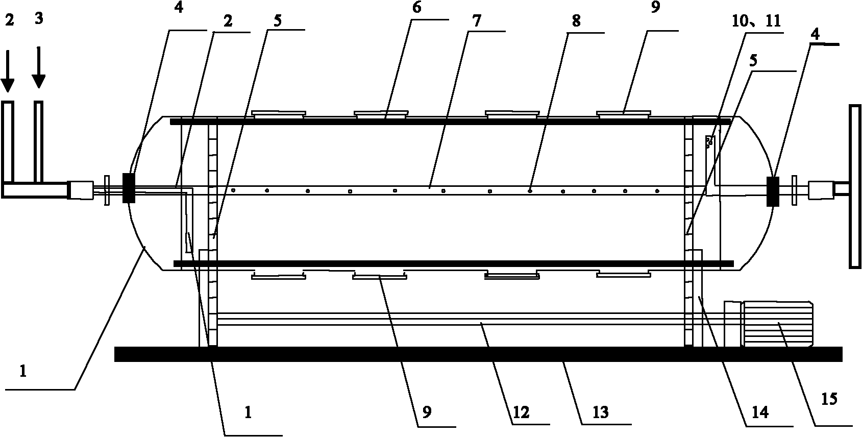
  • Dynamic micro-electrolysis waste water treatment device and water treatment method thereof
  • Dynamic micro-electrolysis waste water treatment device and water treatment method thereof
  • Dynamic micro-electrolysis waste water treatment device and water treatment method thereof

Examples


Embodiment 1

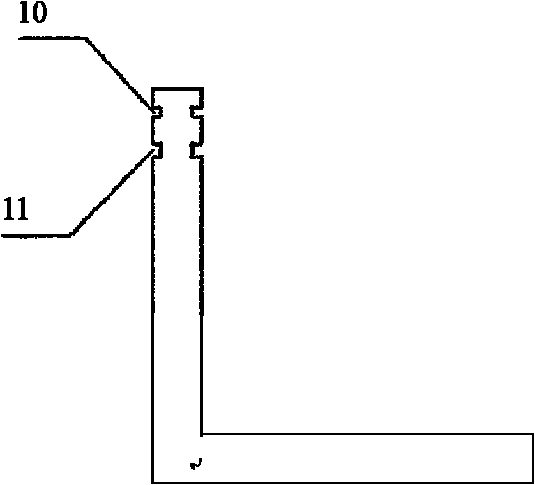
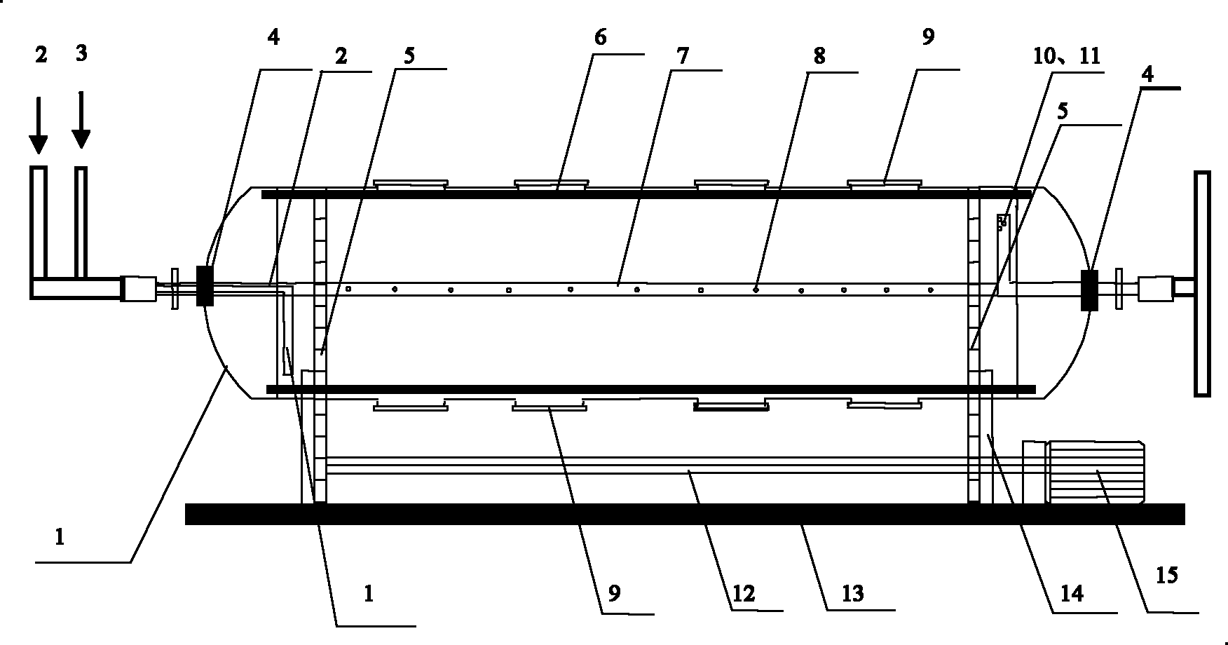
[0022] Such as figure 1 and figure 2 As shown, this embodiment includes: drum reactor 1, water inlet pipe 2, air inlet pipe 3, outlet pipe 11, air outlet pipe 10, transmission belt 5, aeration pipe 7 and support base 14, wherein: drum reactor 1 is installed on On the support base 14 of the base 13, the driving motor 15 is fixed on the base 13 and the transmission shaft 12 of the driving motor 15 is connected with the transmission belt 5 and the drum reactor 1 in turn to realize the rolling of the drum reactor 1, and the both sides of the drum reactor 1 A sealed rotary interface 4 is provided and connected to the water inlet pipe 2, the air inlet pipe 3 and the water outlet pipe 11 and the air outlet pipe 10 respectively. connect.

[0023] The iron-carbon mixture is filled in the roller reactor 1, and the rolling of the roller reactor 1 is driven by the driving motor 15 to form a dynamic iron-carbon bed. The scraper 6 in the roller reactor 1 is conducive to the dispersion of...

Embodiment 2

[0028] The roller reactor 1 that adopts plexiglass to make by embodiment 1, the effective volume of roller reactor 1 is 10 liters, iron filings and gac (solid-to-liquid ratio 5: 8) are packed into, the COD6000mg / amantadine hydrochloride water of pH 1.0 Introduce into the drum reactor 1, feed water continuously, start the motor 15, drive the reactor to rotate, and aerate through the air inlet pipe 3; the waste water undergoes micro-electrolysis reaction in the drum reactor, and the residence time is controlled at 0.5 hours. The waste water is discharged through the water outlet 11; the waste water treated by the above method has a COD removal rate of 40%

Embodiment 3

[0030] The roller reactor 1 that adopts plexiglass to be made by embodiment 1, the effective volume of roller reactor 1 is 10 liters, iron filings and gac (solid-to-liquid ratio 5: 8) are packed into, the COD6000mg / amantadine hydrochloride water of pH 5.0 Introduce into the drum reactor 1, feed water continuously, start the motor 15, drive the reactor to rotate, and aerate through the intake pipe 3; the waste water is subjected to micro-electrolysis reaction in the drum reactor, and the residence time is controlled at 6 hours. The waste water is discharged through the water outlet 11; the waste water treated by the above method has a COD removal rate of 35%. The water treated by the drum-type iron-carbon micro-electrolysis reaction device is added with H2 o 2 3ml / L, Fenton oxidation for 20min, the COD removal rate increased by 10%.


PUM


Abstract

The invention relates to a dynamic micro-electrolysis waste water treatment device and a water treatment method thereof. The device comprises a cylinder reactor, a water inlet pipe, an air inlet pipe, a water outlet pipe, an air outlet pipe, a transmission belt, an aerated conduit and a support base, wherein the cylinder reactor is mounted on the support base; an output shaft of a driving motor is connected to the transmission belt and the cylinder reactor in turn so as to rotate the cylinder reactor; a sealing rotatable interface is arranged on two sides of the cylinder reactor and is respectively connected to the water inlet pipe, the air inlet pipe, the water outlet pipe and the air outlet pipe; and an exit of the water outlet pipe and the aerated conduit are both arranged in the cylinder reactor and are connected to the sealing rotatable interface. Compared with the prior art, the invention has higher treating efficiency and oxidizing capacity and is more convenient to charge, discharge, maintain and clean the cylinder.

Description

technical field [0001] The invention relates to a device in the technical field of water treatment and a treatment method thereof, in particular to a dynamic micro-electrolysis wastewater treatment device and a water treatment method thereof. Background technique [0002] Over the years, my country has made great achievements in the treatment of urban domestic sewage and biodegradable industrial wastewater, and has made important contributions to my country's environmental protection. In recent years, with the rapid development of the chemical, pharmaceutical, and petrochemical industries, there are more and more organic wastewater with less water but high concentration, refractory degradation, and high salinity. This type of wastewater has become a new public hazard. Only a single biochemical treatment is used. It is simply impossible to meet the national emission requirements. For the treatment of such high-concentration refractory wastewater, pretreatment technology must...

Claims


Application Information

Patent Timeline
Patent Type & Authority Applications(China)
IPC IPC(8): C02F1/461
Inventor 周保学刘晓冉李金花郑耿涛宋永会
Owner SHANGHAI JIAO TONG UNIV
Learn More