Low-voltage reference source with low flicker noise and high power-supply suppression

A technology with high power supply suppression and flicker noise, applied in the direction of adjusting electrical variables, control/regulation systems, instruments, etc., can solve problems such as increasing the complexity of circuit design or process processing, to save voltage margin, reduce flicker noise, Improve the effect of power supply rejection

Inactive Publication Date: 2011-02-23
ZHEJIANG UNIV
View PDF8 Cites 22 Cited by
  • Summary
  • Abstract
  • Description
  • Claims
  • Application Information

AI Technical Summary

Problems solved by technology

Among the existing methods for reducing the flicker noise of the reference source, the Chinese patent CN101630173 provides a way to reduce the flicker noise by periodically switching between the strong inversion region and the cut-off region of the MOS transistor, and the U.S

Method used


Image

  • Low-voltage reference source with low flicker noise and high power-supply suppression
  • Low-voltage reference source with low flicker noise and high power-supply suppression
  • Low-voltage reference source with low flicker noise and high power-supply suppression

Examples


Embodiment 1

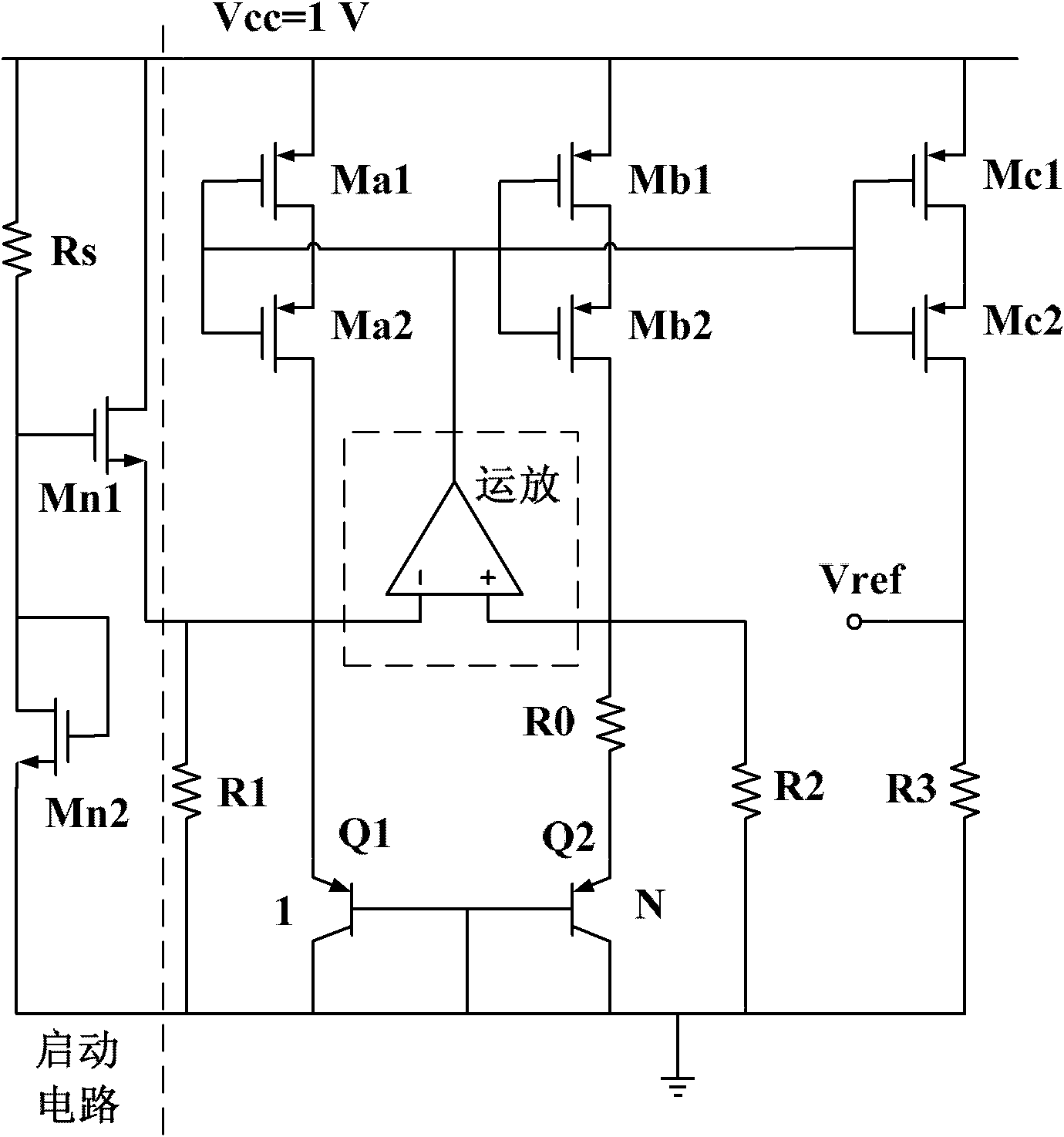
[0025] like figure 1 As shown, the overall circuit of a low-voltage reference source with low flicker noise and high power supply rejection is an embodiment of the present invention, which includes a start-up circuit, a self-cascaded current mirror, an operational amplifier, a temperature coefficient compensation circuit, and a reference output stage circuit .

[0026] The starting circuit is composed of a resistor Rs and two NMOS transistors Mn1 and Mn2. Where Rs is connected between the power supply and the gate of Mn1; the drain of Mn1 is connected to the power supply, and its source is connected to the emitter of the triode Q1; the gate and drain of Mn2 are connected, and its source is grounded.

[0027] The self-cascading current mirror is composed of six low-threshold voltage PMOS transistors Ma1-2, Mb1-2 and Mc1-2, which form three self-cascading current sources, providing the same Taking Ma1 and Ma2 as an example, the two MOS transistors are connected in series, the ...

Embodiment 2

[0043] like Figure 4 As shown, a low-voltage reference source with low flicker noise and high power supply rejection includes a start-up circuit, a self-cascaded current mirror, an operational amplifier, a high-order temperature coefficient compensation circuit, and a reference output stage circuit, wherein the start-up circuit, operational amplifier, and reference The output stage circuit is the same as that in Embodiment 1; the self-cascading current mirror adds one self-cascading current source Ms1-2, and its realization and connection method are consistent with the three groups of current sources in Embodiment 1; the high Compared with the temperature coefficient compensation circuit in Embodiment 1, a transistor Q3 and two resistors R4 and R5 are added. The emitter-base area of ​​the added transistor Q3 is the same as that of Q1, the base and collector of Q3 are grounded, the emitter is connected to a newly added self-cascading current source, and the resistors R4 and R5...


PUM


Abstract

The invention discloses a low-voltage reference source with low flicker noise and high power-supply suppression. The low-voltage reference source comprises a starting circuit, a self-cascaded operational amplifier, a temperature coefficient compensating circuit and a reference output-level circuit, wherein the self-cascaded structures; and the self-cascaded the low-voltage reference source, the power-supply suppression is improved and the flicker noise is reduced at the same time; an input metal oxide semiconductor (MOS) pipe in the operational amplifier is a primary MOS pipe, so that the flicker noise is further reduced and voltage redundancy is saved in a low-voltage circuit at the same time; and after the temperature coefficient compensating circuit is expanded into a high-level temperature coefficient compensating circuit, the change of reference source output voltage with the temperature is further reduced and the stability of the reference source output voltage is improved.

Description

technical field [0001] The invention belongs to the field of integrated circuit design, in particular to a voltage reference source with high power supply rejection ratio and low flicker noise working at low voltage, and the design is realized based on CMOS technology. Background technique [0002] The reference source is an indispensable module in analog integrated circuits and mixed-signal integrated circuits. It is widely used in low-dropout regulators, switching power supplies, data converters, etc. These circuits generally require that the output of the reference source does not vary with temperature and power supply voltage. Variety. The current mainstream reference sources all use the thermal voltage V T The positive temperature coefficient of the bipolar transistor (triode) and the base-emitter V BE Compensate the negative temperature coefficient of the voltage to achieve a lower temperature coefficient, and at the same time, other technologies can be added to perf...

Claims


Application Information

Patent Timeline
IPC IPC(8): G05F1/567
Inventor 张昊王昊
Owner ZHEJIANG UNIV
Why Eureka
Try Eureka