Film coating source, vacuum film coating device and film coating process thereof

A vacuum coating and vacuum chamber technology, applied in the field of vacuum coating equipment and its coating process, can solve the problems of poor uniformity of film thickness distribution in the substrate plane, low material utilization rate, etc., and achieve good pattern accuracy, uniform light-emitting performance, good film Thick and even effect

Inactive Publication Date: 2011-03-23
无锡虹彩科技发展有限公司 +1
View PDF8 Cites 14 Cited by
  • Summary
  • Abstract
  • Description
  • Claims
  • Application Information

AI Technical Summary

Problems solved by technology

However, this coating method has the problems of low material utilization rate and poor uniformity of film thickness distribution on the substrate surface.

Method used


Image

  • Film coating source, vacuum film coating device and film coating process thereof
  • Film coating source, vacuum film coating device and film coating process thereof
  • Film coating source, vacuum film coating device and film coating process thereof

Examples


Embodiment

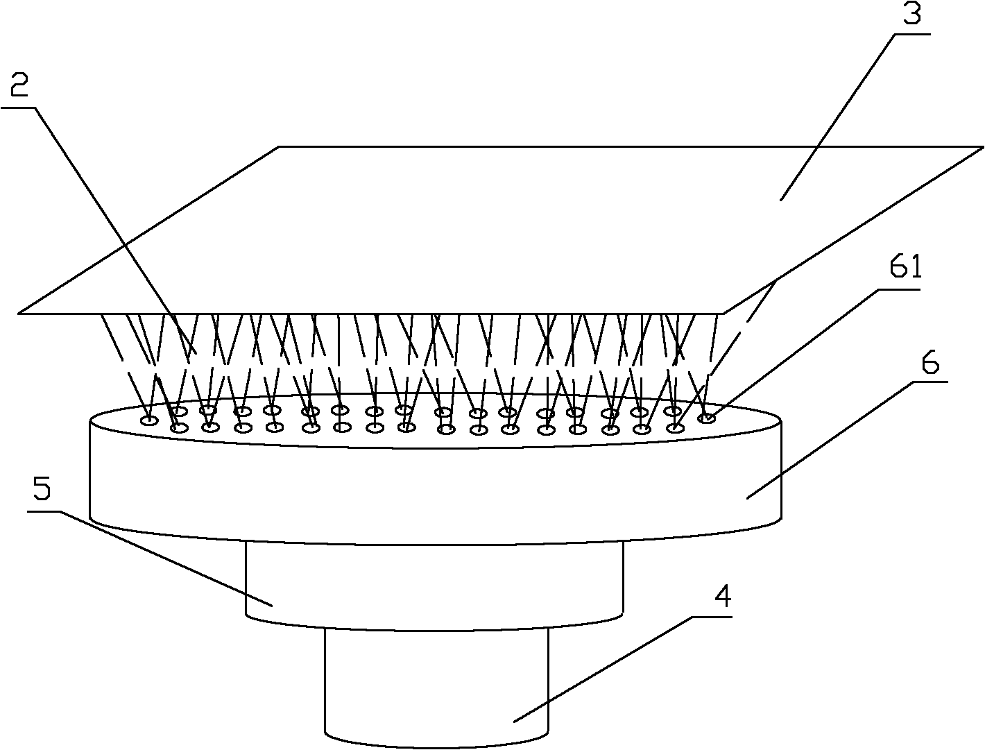
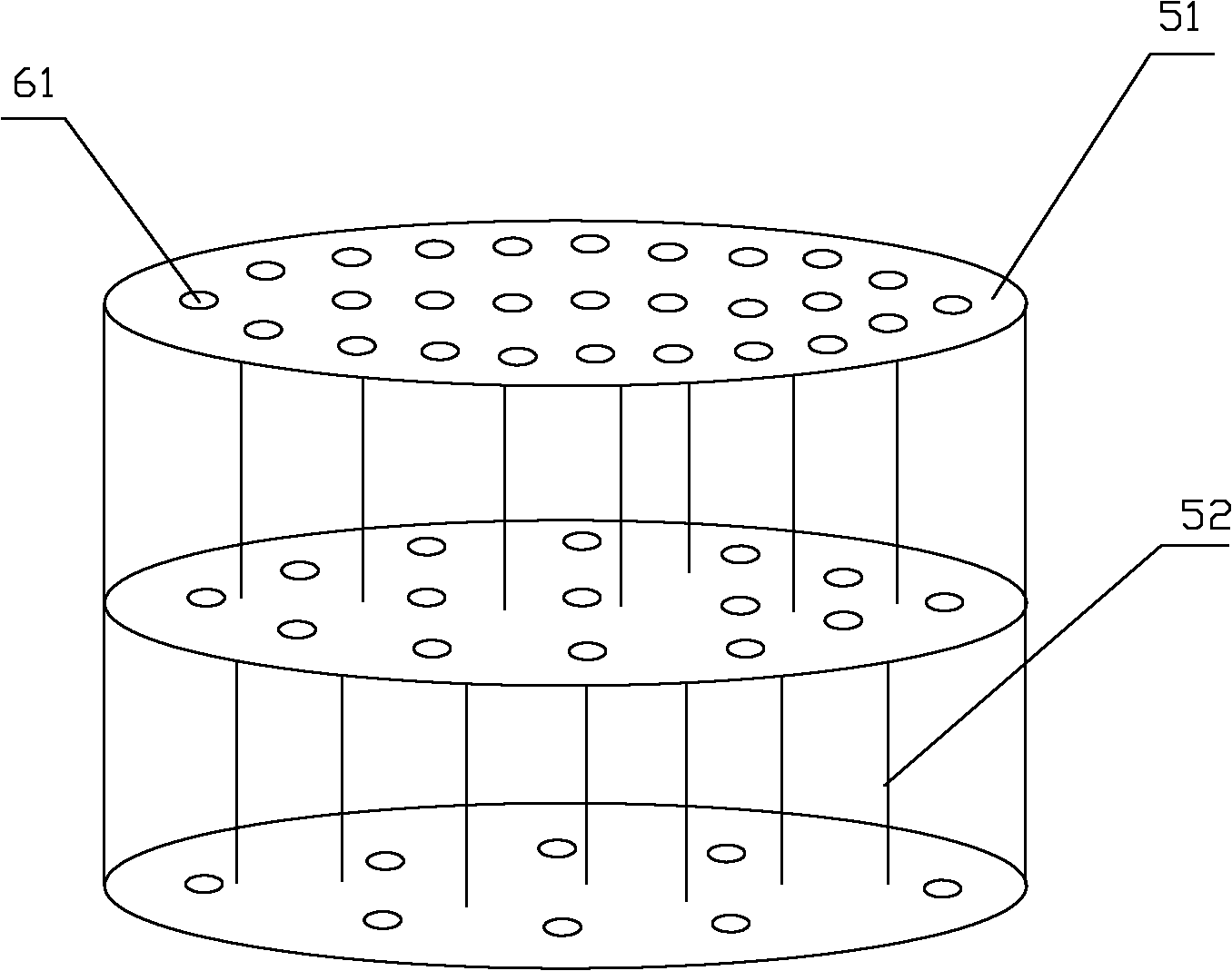
[0038] use figure 2 In the coating source structure shown, the container part 4 is made of copper, and a layer of nickel is plated on it to improve the uniformity of heat conduction. The evaporative airflow adjustment part 5 adopts the structure of two layers of injection plates 51, the first layer of injection plates 51 is seamlessly connected with the container part 4, the second layer of injection plates 51 is also seamlessly connected with the first layer of injection plates 51, and the second layer of injection plates 51 is also seamlessly connected with the first layer of injection plates 51. The distance between the spray plate 51 and the spray plate 51 of the first layer is 7 cm. The diameter of the injection port 61 on the first layer of injection plate 51 is 4cm, and 2 injection ports are evenly arranged on the first layer of injection plate 51, and 4 injection ports 61 are evenly arranged on the second layer of injection plate 51, and its diameter is 3cm. There a...


PUM


Abstract

The invention provides a film coating source and a vacuum film coating device thereof which can carry out even evaporation on a base plate with a large area. The film coating source is provided with a container part, a heating device, an evaporation airflow adjusting part and an evaporation coating top plate, wherein the evaporation airflow adjusting part is in a porous layered structure and is used for controlling the direction and distribution of the evaporation airflow; and evenly distributed jet orifices are arranged on the evaporation coating top plate and used for jetting the evaporation airflow. By the airflow adjusting part of the porous layered structure, the invention furthest enlarges the evaporation coating area of the evaporation coating top plate, and enables the material to be deposited on the surface of the base plate as evenly as possible, thereby achieving the effect of evaporation with high evenness in a large area. When the invention is used for carrying out vacuum film coating of organic materials on an organic light-emitting diode (OLED), especially for carrying out film coating on the base plate with a larger area, a film coating layer with good pattern accuracy and even film thickness can be obtained, thereby ensuring even luminescent properties and color balance of the OLED.

Description

technical field [0001] The invention relates to a vacuum coating device, in particular to a vacuum coating device for OLED organic material coating and a coating process thereof. Background technique [0002] As a self-illuminating electronic component, organic electroluminescence (OLED: Organic Light Emission Diodes) shows that the light-emitting principle of the lighting component is a new type of direct conversion of electrical energy into light energy with the help of organic semiconductor functional materials under the action of a DC electric field. Photoelectric information technology. The OLED element, which has attracted attention in the fields of displays and lighting as a self-luminous thin display element or a surface-emitting source, has a basic structure in which a first electrode is formed on a substrate, and on the first electrode is formed a layer of different An organic layer thin film layer composed of an organic compound, and a second electrode is formed ...

Claims


Application Information

Patent Timeline
IPC IPC(8): C23C14/26
Inventor 李金川李崇田朝勇
Owner 无锡虹彩科技发展有限公司
Why Eureka
Try Eureka