Screw cascade waste heat energy generating device and generating method

A power generation device and cascade technology, which is applied in the direction of steam engine devices, machines/engines, mechanical equipment, etc., can solve the problems of insufficient low-temperature heat recovery, limited thermal energy utilization rate, and low energy conversion efficiency, so as to improve energy conversion efficiency and realize The effect of power generation efficiency and resource utilization improvement

Inactive Publication Date: 2011-03-30
TIANJIN UNIV
View PDF5 Cites 16 Cited by
  • Summary
  • Abstract
  • Description
  • Claims
  • Application Information

AI Technical Summary

Problems solved by technology

However, the energy conversion efficiency is low and the utilization rate of heat energy is limited.
The current low-temperature power generation technology of the organic refrigerant Rankine cycle generally uses a steam turbine as an expander and uses superheated gas to expand; in addition, the temperature drop of the heat source for single-stage low-temperature power generation cannot be too large, otherwise the power generation efficiency will be reduced, so the recovery of low-temperature heat insufficient

Method used


Image

  • Screw cascade waste heat energy generating device and generating method
  • Screw cascade waste heat energy generating device and generating method

Examples


Embodiment 1

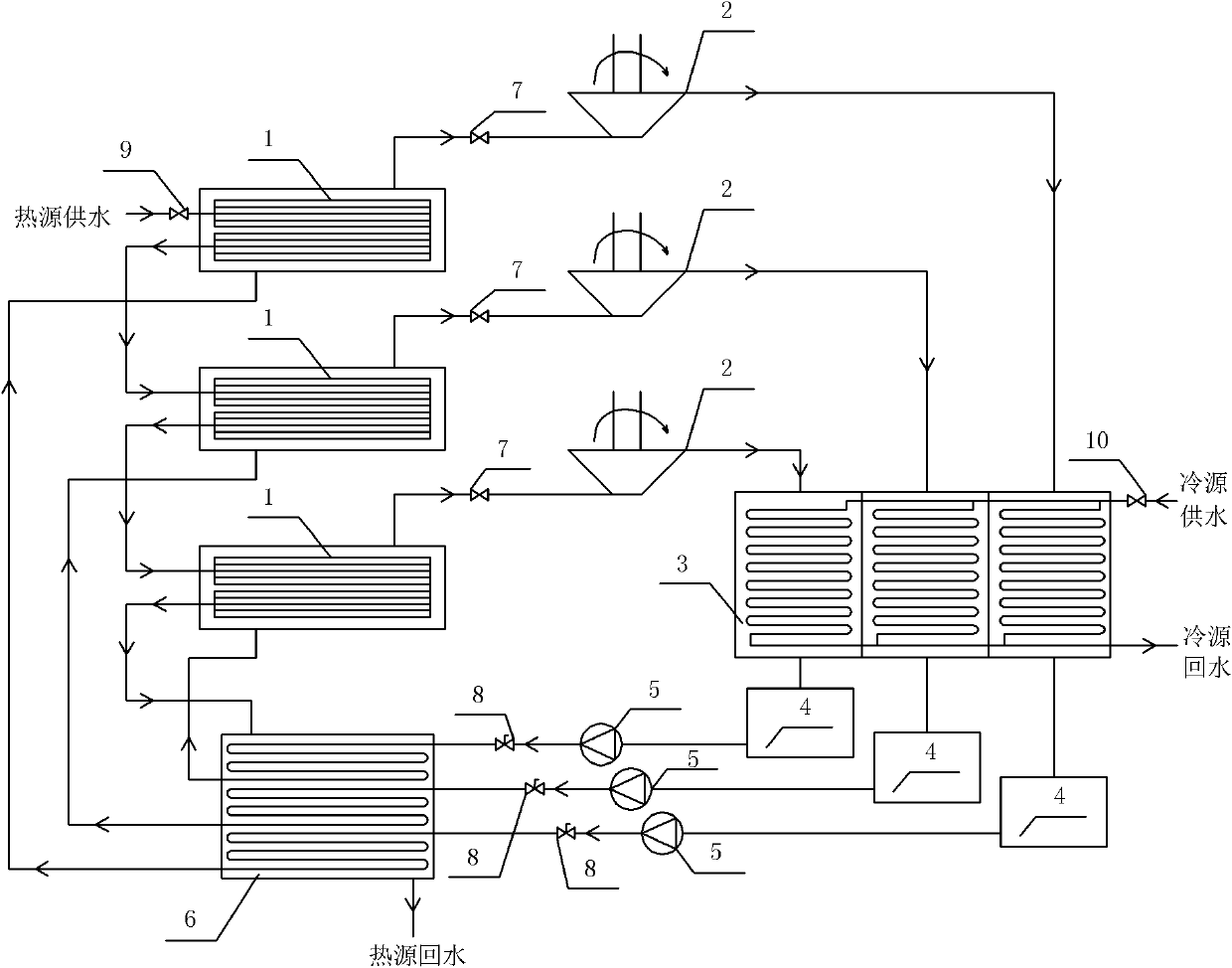
[0028] Using a three-stage generating set, the three-stage generating set runs the following steps:

[0029](1) Let the cold water circulate in parallel through the condensers of the three-stage generator sets and make the hot water pass through the tube side of the flooded evaporator 1 and the tube side of a shell-and-tube preheater 6 of the generator sets of all levels arranged in series in sequence Shell side, the tube side of the shell-and-tube preheaters of the generator sets at all levels are independently arranged in a shell; (2) Start the three-stage generator sets one by one, and each generator set runs the following steps: the working of each generator set The supercooled liquid of the organic working medium at the outlet of the mass circulation pump 5 enters the tube side of the shell-and-tube preheater 6, and after the heat absorption reaches saturation, it enters the shell side of the flooded evaporator 1 of each generating set to form boiling heat exchange and eva...

Embodiment 2

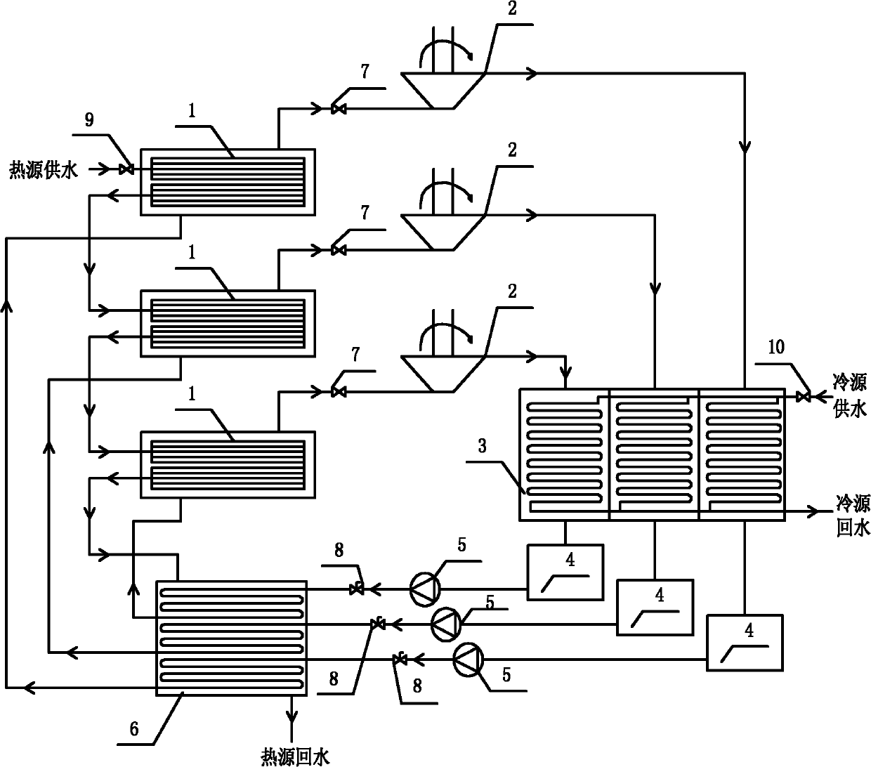
[0032] Using a secondary generating set, the secondary generating set operates the following steps:

[0033] (1) Let the cold water circulate through the condensers of the two-stage generator sets in parallel and make the hot water pass through the tube side of the flooded evaporator 1 and the tube side of a shell-and-tube preheater 6 of the generator sets at all levels arranged in series in sequence Shell side, the tube side of the shell-and-tube preheater of the generator sets at all levels are independently arranged in a shell; (2) Start the second-level generator sets one by one, and each generator set runs the following steps: the working of each generator set The supercooled liquid of the organic working medium at the outlet of the mass circulation pump 5 enters the tube side of the shell-and-tube preheater 6, and after the heat absorption reaches saturation, it enters the shell side of the flooded evaporator 1 of each generating set to form boiling heat exchange and evap...


PUM


Abstract

The invention discloses a screw cascade waste heat energy generating device and a screw cascade waste heat energy generating method. The device comprises at least one stage of generator sets, and each stage of generator sets comprises a flooded evaporator, a shell and tube preheater, a reservoir, a condenser and a screw expansion machine, wherein a shell pass outlet of the shell and tube preheater is communicated with the tube pass of the flooded evaporator, and a tube pass outlet of the shell and tube preheater is communicated with the shell pass of the flooded evaporator; an opening at the bottom of the reservoir is communicated with a tube pass inlet of the shell and tube preheater through a circulating pipeline on which a working medium circulating pump and a check valve are arranged; the condenser is connected above the reservoir; and a rotating shaft of the screw expansion machine is connected with a rotating shaft of a synchronizing generator, a shell pass outlet of the flooded evaporator is connected with an inlet of the screw expansion machine through a pipeline on which a flow regulating valve is arranged, and an outlet of the screw expansion machine is communicated with the shell pass of the condenser. By using the device and the method, the heat power generation with large temperature drop at low temperature is realized, and the conversion efficiency of low-temperature heat energy is improved.

Description

technical field [0001] The present invention relates to a power generation device and a power generation method thereof, in particular to a cascade conversion of various low-temperature thermal energy, such as renewable low-temperature energy such as geothermal energy, solar energy, and industrial waste heat, etc., to convert low-quality thermal energy into high-quality electrical energy. and its methods. Background technique [0002] In the current development of low-temperature thermal power generation technology, there are two forms: single-cycle power generation directly using steam as the circulating working medium and double-cycle power generation using organic working medium to indirectly convert heat energy; organic working medium double-cycle power generation is more suitable for low-temperature heat sources and is subject to people's attention. However, the energy conversion efficiency is low, and the utilization rate of heat energy is limited. The current low-te...

Claims


Application Information

Patent Timeline
Patent Type & Authority Applications(China)
IPC IPC(8): F01K27/02F01K11/02F01D15/10
Inventor 张于峰魏莉莉陈信鑫穆永超杨晓晨
Owner TIANJIN UNIV
Why Eureka
Try Eureka