
Ultra-thin wide spectrum holographic antenna

A holographic antenna and wide-spectrum technology, applied in the field of holographic optical components, can solve the problems of restricting the development of space optical communication technology, increasing costs, and bulky optical lenses, and achieve integration and miniaturization. The requirements for the use environment are small, physical The effect of stable performance

Active Publication Date: 2011-03-30
BEIJING INSTITUTE OF TECHNOLOGYGY
View PDF4 Cites 20 Cited by
  • Summary
  • Abstract
  • Description
  • Claims
  • Application Information

AI Technical Summary

Problems solved by technology

However, with the increase in the amount of information transmitted by wireless communication and the interference of various obstacles in the propagation space, the requirements for the aperture of the collection lens continue to increase. The increase in aperture is accompanied by the strengthening of the collection / transmission signal but also brings a series of problems. technical challenge
Large-diameter optical lenses are difficult to manufacture, resulting in a substantial increase in cost, and large-sized optical lenses are generally bulky, which brings difficulties to installation such as adjustment and alignment, greatly affects the effect of optical antennas, and limits the space Development of Optical Communication Technology

Method used


Image

  • Ultra-thin wide spectrum holographic antenna
  • Ultra-thin wide spectrum holographic antenna
  • Ultra-thin wide spectrum holographic antenna

Examples


Embodiment Construction

[0015] The specific technical solution of the ultra-light and wide-spectrum holographic antenna of the present invention will be described in detail below with reference to the accompanying drawings. However, the present invention can be implemented in many different forms and should not be construed as being limited to the exemplary embodiments described herein.

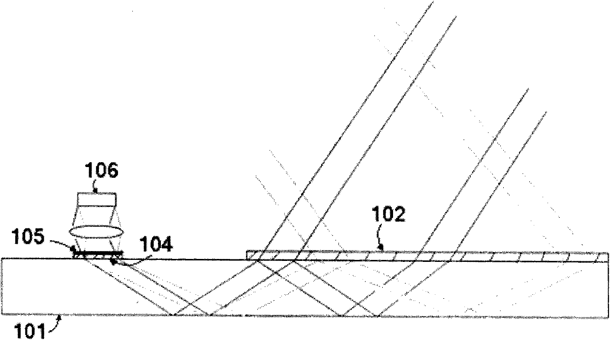
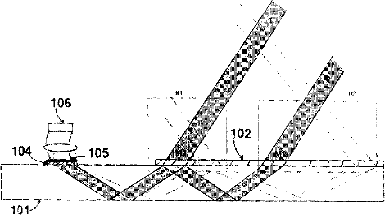
[0016] Such as figure 1 As shown, the holographic antenna of the present invention includes: a propagation substrate (101), a coupling grating H 0 (102), and a group of channel gratings H 1 ~H m (103). Taking the process of collecting signal light for communication as an example, the coupling grating is placed on the upper surface of the propagation substrate. At this time, the coupling grating is a transmission type grating. In order to increase the diffraction efficiency, the antenna of the present invention can also adopt another structure. The coupling grating It is set as a reflective grating, placed on the ...


PUM


Abstract

The invention relates to a holographic optical antenna device which comprises a light ray propagation base, at least one coupling grating and at least one channel grating are recorded on the base, wherein the coupling grating is an input grating and used for leading a space optical with a certain aperture angle coupling to enter into the base, transforming optical waves with different wavelengths in a finite aperture to plane waves with a certain tilted phase, carrying out full-reflection propagation in the base, and carrying out a certain spectrum separation on incident optical waves with the different wavelengths. At least one channel grating can lead the plane waves which are incident on the channel grating to couple and emerge, and further lead the waves to enter into a follow-up photoelectric conversion and signal processing circuit, thereby obtaining information carried in input light and realizing the functions of the antenna. The optical antenna has the advantages of low manufacturing cost and small installation and adjustment difficulty, does not depend on a lens system and can simultaneously meet the requirements on ultra-thin size and large aperture.

Description

technical field [0001] The invention relates to a holographic optical element, in particular to an ultra-thin wide-spectrum holographic antenna to realize the function of an optical antenna in free space and perform photoelectric conversion. Background technique [0002] While the optical fiber communication technology used on the ground is maturing day by day, people focus their attention on free space optical communication. Free space optical communication is the product of optical fiber communication and wireless communication. It uses laser as a carrier and uses optical pulse modulation signal to transmit information in vacuum or atmosphere. It includes satellite optical communication, satellite-ground optical communication and atmospheric optical communication. Compared with the traditional wireless communication method using electromagnetic waves, free space optical communication has the advantages of narrow emission beam, large information capacity, small emission dev...

Claims


Application Information

Patent Timeline
Patent Type & Authority Applications(China)
IPC IPC(8): G02B6/34G02B5/18
Inventor 王涌天刘冬梅刘娟潘奕捷赵浩之谢敬辉
Owner BEIJING INSTITUTE OF TECHNOLOGYGY
Learn More