
Method of determining particle size distribution of fine particles contained in metallic material

A metal material, particle size distribution technology, applied in the direction of material separation, particle size analysis, material analysis through optical means, etc., can solve the problems of incorrectness, comparison of pulse intensity, inability to apply luminescence analysis method, etc., and achieve accurate particle size distribution Effect

Active Publication Date: 2011-04-13
NIPPON STEEL CORP
View PDF3 Cites 6 Cited by
  • Summary
  • Abstract
  • Description
  • Claims
  • Application Information

AI Technical Summary

Problems solved by technology

[0011] However, since the assumptions in the methods described in Patent Document 2 and Non-Patent Document 2 are incorrect, it cannot be said that the accuracy is high
In other words, as long as the actual discharge trace with a diameter of several mm is observed, it is naturally assumed that "one pulse emits light from multiple inclusions (oxides)", and the above assumption is incorrect.
[0012] In addition, in these luminescence analysis methods, particles such as inclusions that contribute to luminescence are in principle larger than several μm, so as long as the particles are not such a size, it is impossible to perform pulse intensity with the solid solution components contained in the matrix. Compare
In other words, the luminescence analysis method cannot be applied to fine particles smaller than several μm, and accurate analysis cannot be performed.
[0013] In this way, it is very important to quickly and accurately quantitatively analyze the particle size, frequency, and composition of particles in metals in quality control of metal materials, but this quantitative analysis has not been possible with conventional technologies.

Method used


Image

  • Method of determining particle size distribution of fine particles contained in metallic material
  • Method of determining particle size distribution of fine particles contained in metallic material
  • Method of determining particle size distribution of fine particles contained in metallic material

Examples


Embodiment

[0091] Next, examples of the present invention will be described. However, the present invention is not limited to the conditions employed in Examples.

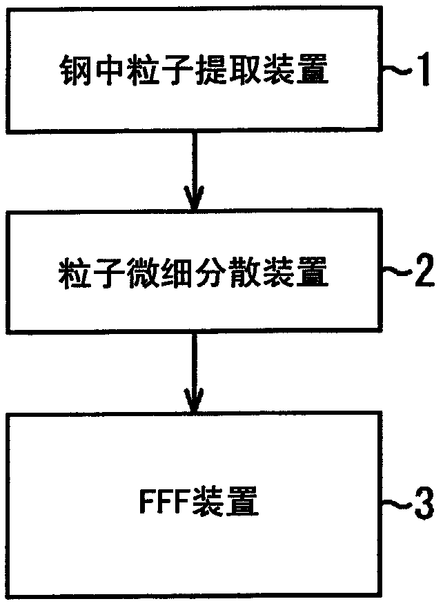
[0092] according to figure 1 In the flow shown, after the fine particles in the iron and steel material are extracted and dispersed in the solution, the size and number density are measured by the fine particle analysis method of this embodiment with the FFF apparatus.

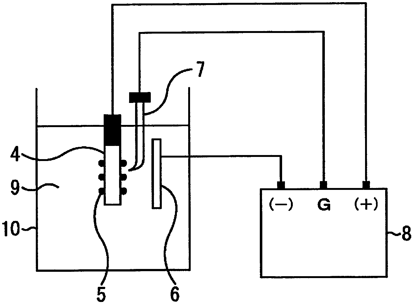
[0093] High Si-based steel samples (Si: 3% by mass, Mn: 0.1% by mass, S: 0.03% by mass, Al: 0.03% by mass, N: 0.01% by mass) were processed into a size of 20mm×40mm×0.3mm, and passed Chemical polishing removes oxide films such as iron oxide scale on the surface to expose the metal layer. At this time, regarding the high-Si-based steel samples, samples were taken from steel materials produced under the conditions that the heating temperature in the manufacturing process was specified as a normal temperature (1000°C) and a high temperature (1100°C) about 100°...


PUM

PropertyMeasurementUnit
sizeaaaaaaaaaa

Abstract

The invention provides a method of determining particle size distribution of fine particles contained in metallic material. The method comprises: a step in which fine particles contained in a metallic material to be examined are isolated by extraction with a solution using a means of extraction for fine-particle isolation; a step in which the fine particles isolated by extraction are dispersed ina solvent to prepare a dispersion and the dispersion is separated into fine-particle dispersions having respective size ranges with a field-flow fractionation device; and a step in which the fine-particle dispersions having respective size ranges are irradiated with a laser light to determine the absolute value of the size of the fine particles of each dispersion from the angle dependence of the resultant reflected-light intensity, and the number density of the fine particles is determined from the reflected-light intensity.

Description

technical field [0001] The present invention relates to a particle size measurement method of particles (precipitates and non-metallic inclusions) in metal materials by field flow separation (FFF: Field Flow Fractionation) method. Background technique [0002] In recent years, there has been an increasing demand for higher quality metal materials. Relatively large inclusions generated during the deoxidation process of steel are the cause of serious deterioration of steel quality. For example, alumina-based oxides cause various defects such as surface defects in thin steel sheets for automobiles, cracks in beverage can manufacturing, and wire breakage in wire drawing of wire products. Therefore, various efforts have been made to reduce the amount and size of such inclusions. [0003] On the other hand, various attempts have been made to further improve the quality of steel products by artificially increasing or decreasing the amount and size of fine precipitates. For examp...

Claims


Application Information

Patent Timeline
Patent Type & Authority Applications(China)
IPC IPC(8): G01N15/02
CPCG01N33/20G01N30/0005G01N2021/4704G01N15/0205G01N33/2022
Inventor 水上和实村上健一新井聪森重宣乡久保祐治本间穗高难波英一
Owner NIPPON STEEL CORP
Learn More