Radio frequency optical fiber transmission optical workstation for two-way network transformation of cable television

A technology of cable television and two-way network, which is applied in radio frequency optical fiber transmission optical workstation, hybrid optical fiber coaxial cable network two-way network transformation, based on the field of cable TV two-way transmission equipment, can solve the problem of destroying uplink channel data transmission, high average cost per household, video Image distortion, voice and other problems

Inactive Publication Date: 2011-05-04
CHANGSHU GAOSHIDA PHOTOELECTRICITY TECH
View PDF6 Cites 21 Cited by
  • Summary
  • Abstract
  • Description
  • Claims
  • Application Information

AI Technical Summary

Problems solved by technology

[0009] 1. Noise pooling: For most cable TV operators, upstream noise is a common problem, especially in low frequency bands (<65MHz)
Usually this kind of noise is caused by electronic motors, lightning, HAM, short-wave broadcasting or even sunspots, terminal boxes in the user's home, the quality of cables buried in the wall, private connection of non-standard parts, tape connection lines at various interfaces in the home, etc. It will destroy the data transmission of the uplink channel (reverse return channel), so as to reduce the user's communication quality, especially in real-time business situations such as video or IP voice, noise interference will cause data transmission delay and jitter, resulting in video Distorted picture or discontinuous voice
This requires that the coaxial cable connectors in the HFC network have a high electrical connection quality factor, and the technical support required for maintenance and operation troubleshooting is difficult to properly solve in the short term in most areas of our country
[0010] 2. Low bandwidth: using CMTS for two-way transformation, it is necessary to carry out two-way transformation on the opti

Method used


Image

  • Radio frequency optical fiber transmission optical workstation for two-way network transformation of cable television
  • Radio frequency optical fiber transmission optical workstation for two-way network transformation of cable television
  • Radio frequency optical fiber transmission optical workstation for two-way network transformation of cable television

Examples


Example Embodiment

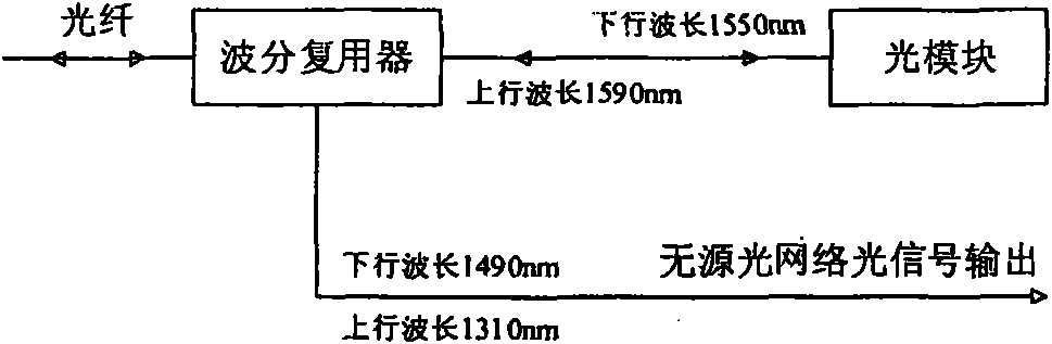
[0034] see figure 2 : The connection between the wavelength division multiplexer and the optical module is to separate the optical signal from the front end of the cable TV. One channel of the downlink wavelength 1550nm and the uplink wavelength 1590nm optical signal is connected to the optical module, and the other channel of the downlink wavelength 1490nm and the uplink wavelength 1310nm optical signal is connected to the PON optical signal interface.

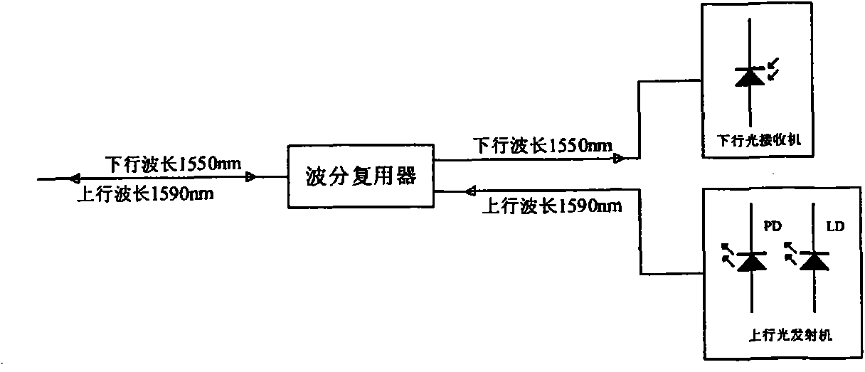
[0035] see image 3 : The optical module consists of a downlink optical receiver and an uplink optical transmitter. The optical module is JZPI-PL. The optical module is connected with a wavelength division multiplexer to transmit the downlink wavelength 1550nm optical signal to the downlink optical receiver of the optical module. The uplink optical transmitter sends the 1590nm optical signal to the wavelength division multiplexer.

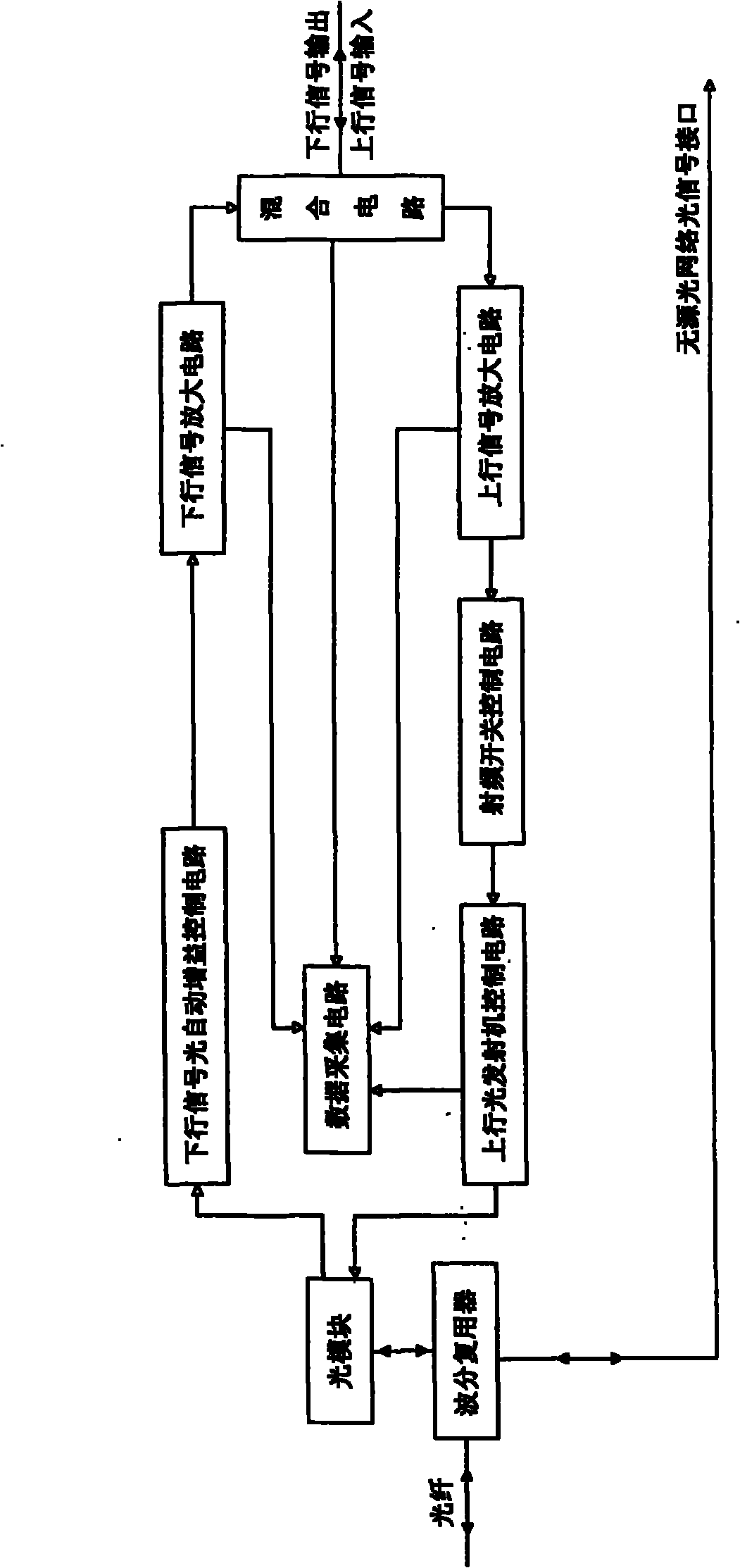
[0036] see Figure 4 : The downlink signal optical automatic gain control circuit is withi...


PUM


Abstract

The invention relates to a radio frequency optical fiber transmission optical workstation for two-way network transformation of a cable television, which belongs to the field of the cable televisions. The radio frequency optical fiber transmission optical workstation comprises a wavelength division multiplexer, an optical module, a downlink signal optical automatic gain control circuit, a downlink signal amplification circuit, an uplink signal amplification circuit, a radio frequency switching control circuit, an uplink optical transmitter control circuit, a mixing circuit and a data collection circuit. The radio frequency optical fiber transmission optical workstation has the advantages of small noise convergence, high bandwidth, property of being in line with IP-lization, low transformation cost per household and high reliability, and is convenient for upgrading and expansion.

Description

technical field [0001] The invention relates to a radio frequency optical fiber transmission (RFoG RF over glass) optical workstation used for the transformation of the two-way network of cable television, belonging to the technical field of cable television, in particular to a two-way transmission based on cable television for the transformation of a two-way network of a hybrid optical fiber coaxial cable network equipment. Background technique [0002] China Cable Television (CATV, Cable Television) has never faced challenges and development opportunities like it does today. The core business of CATV is facing direct competition from IPTV and satellite live broadcast, and its users are no longer satisfied with passive viewing of programs. , put forward diversified interactive entertainment requirements; the development of domestic digital TV in recent years has brought unprecedented development opportunities to the radio and television system. It provides a brand-new inte...

Claims


Application Information

Patent Timeline
IPC IPC(8): H04N7/22H04B10/12H04B10/2575
Inventor 章冠华陆炯陈鑫邵晓刚
Owner CHANGSHU GAOSHIDA PHOTOELECTRICITY TECH
Why Eureka
Try Eureka