10<5> K/cm temperature gradient directional solidification device and directional solidification method

A technology of directional solidification and temperature gradient, which is applied in the field of material processing engineering, can solve the problems of non-conductive high melting point materials such as directional solidification and low temperature gradient, and achieve the effect of good orientation and uniform structure

Active Publication Date: 2011-05-11
NORTHWESTERN POLYTECHNICAL UNIV
View PDF5 Cites 22 Cited by
  • Summary
  • Abstract
  • Description
  • Claims
  • Application Information

AI Technical Summary

Problems solved by technology

[0007] In order to overcome the low temperature gradient existing in the prior art and the inability to directly realize the directional solidification of non-conductive high-melting point materials, the present invention proposes a 10 5 K / cm temperature gradient directional solidification device and directional solidification method

Method used


Image

  • 10&lt;5&gt; K/cm temperature gradient directional solidification device and directional solidification method
  • 10&lt;5&gt; K/cm temperature gradient directional solidification device and directional solidification method
  • 10&lt;5&gt; K/cm temperature gradient directional solidification device and directional solidification method

Examples


Embodiment 1

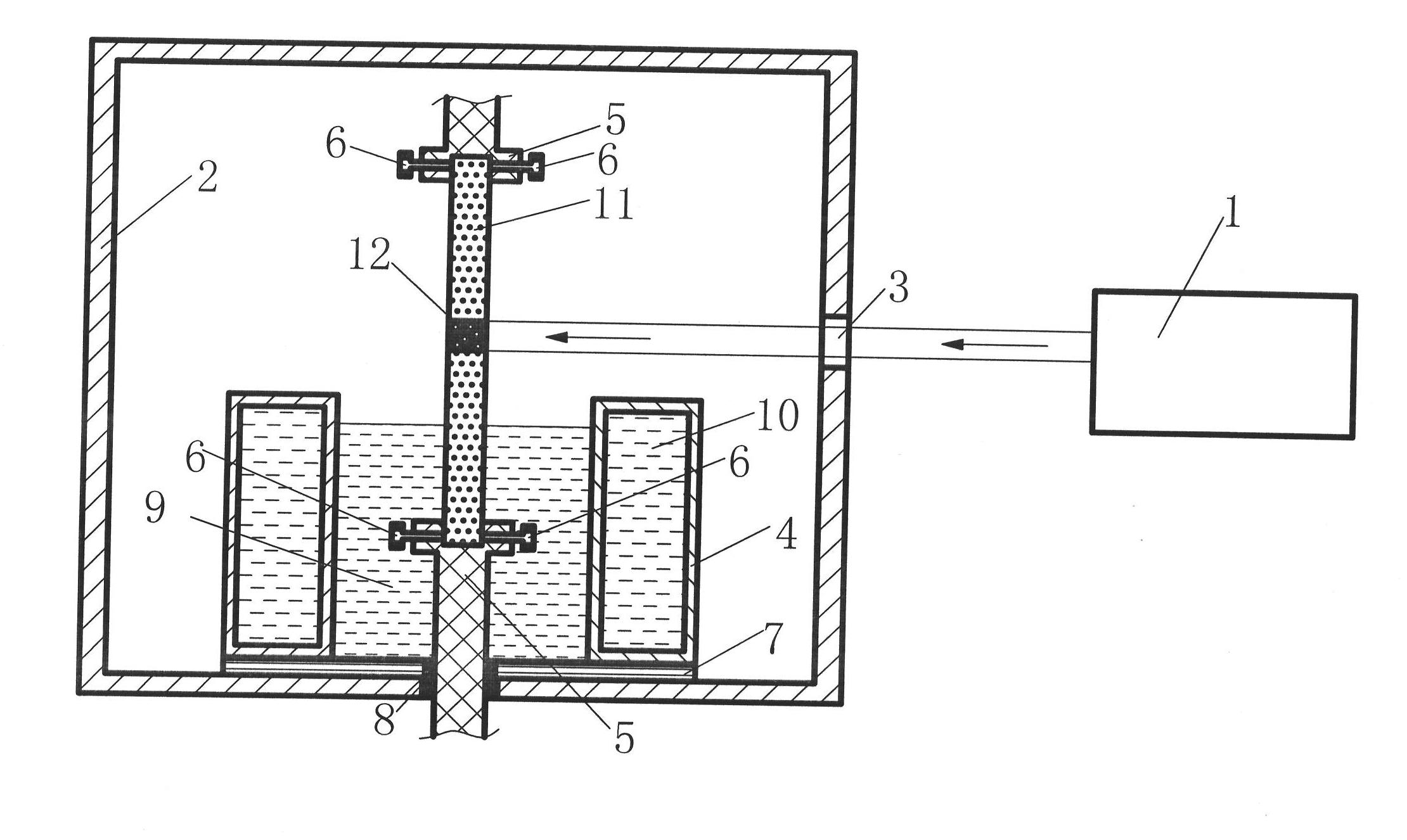
[0031] This example is a method for 10 5 K / cm temperature gradient directional solidification device, including laser 1, vacuum chamber 2, flat lens 3, cooling water cylinder 4, drawing system with cylinder 5, positioning bolt 6, bottom plate 7, sealing ring 8, liquid gallium indium tin alloy 9 A flat lens 3 is installed on the side wall of the vacuum chamber 2; liquid gallium indium tin alloy 9 as a cooling medium is located in the inner cavity of the cooling water cylinder 4. The laser 1 is located on one side of the vacuum chamber 2 .

[0032] The laser produced by the laser 1 of this embodiment enters the vacuum chamber 2 horizontally through the central axis of the flat lens 3, and is perpendicular to and intersects the axis of the drawing system 5 with a cylinder. The flat lens 3 is installed on the side wall of the vacuum chamber 2, The bottom plate 7 is fixed on the lower end of the cooling water cylinder 4 , and the inner hole of the cooling water cylinder 4 and the ...

Embodiment 2

[0037] This embodiment is a method for directional solidification of Al2O3 / YAG binary eutectic with a temperature gradient of 105 K / cm using the directional solidification device with a temperature gradient of 105 K / cm disclosed in Embodiment 1. The specific implementation process of this embodiment includes the following steps,

[0038] The first step is to make a prefabricated body; mix Al2O3 and Y2O3 powders with a purity of 4N according to the Al2O3 / YAG eutectic composition and put them into a mortar, add 10% PVA binder, and mix the powders by conventional methods Mix and grind until there are no agglomerated lumps; put 10 grams of the mixed powder into a mold with an inner cavity size of 68mm×10mm, close the mold and pressurize at 25MPa, hold the pressure for 5 minutes, and press the powder into 68mm×10mm×5mm plate to form the blank of the preform; the blank of the pressed preform is sintered in the atmosphere to increase the strength of the preform, and the required sint...

Embodiment 3

[0041] This embodiment is a method for performing 105K / cm temperature gradient directional solidification on Al2O3 / Y2O3 / ZrO2 ternary hypereutectic crystals using the 105K / cm temperature gradient directional solidification device disclosed in Embodiment 1. The specific implementation process of this embodiment includes the following steps,

[0042] The first step is to make a prefabricated body; mix Al2O3, Y2O3 and ZrO2 three kinds of powders with a purity of 4N according to the molar percentage of 64.6:15.3:20.1 and put them in a mortar, add 10% PVA binder, and use conventional methods Mix and grind the powder until there are no agglomerated hard lumps; put 10 grams of the mixed powder into a mold with an inner cavity size of 68mm×10mm, close the mold and pressurize at 20MPa, hold the pressure for 7 minutes, and press the powder to 68mm×10mm 10mm×5mm plates form the blank of the preform; the blank of the pressed preform is sintered in the atmosphere to increase the strength of...


PUM


Abstract

The invention relates to a 10<5> K / cm temperature gradient directional solidification device and a directional solidification method. The 100000 K / cm temperature gradient directional solidification device is characterized in that laser light generated by a laser horizontally passes through a plate lens to enter a vacuum chamber, intersects vertically the axis of a drawing system, and is used for heating a preform; and liquid gallium-indium-tin alloy serves as cooling medium. The distance between the lower surface of a melting zone and the liquid level of the liquid gallium-indium-tin alloy is 1mm to 5 mm. When directional solidification is performed to the preform, the power of the laser is increased to 200 w to 1400 w. After the preform is zone-melted, a drawing mechanism is started to enable the preform to move at the speed of 1 to 300 microns per second and to be cooled, so that directional solidification of the preform is accomplished. In the invention, laser floating zone melting is combined with liquid metal cooling, so that the obtained oxide eutectic in-situ composite is uniform in structure, fine and compact, has good directing property, and is remarkably improved in mechanical property and other functions, the sizes and the shapes of produced function materials can satisfy the application of various photoelectric components.

Description

technical field [0001] The invention relates to the field of material processing engineering, in particular to a device for realizing directional solidification of high melting point materials and a method for directional solidification. Background technique [0002] The directional solidification method occupies a high position in the research of material structure and performance, as well as in the preparation technology of advanced materials. The complex solidification phenomenon in industrial production can be abstracted, and the solidification behavior of materials can be quantitatively described through controllable parameters such as temperature gradient and solidification rate, which creates conditions for people to deeply understand the structure formation of materials and the relationship between structure and performance. In addition, directional solidification is also an important link in the preparation methods of advanced materials. For example, the preparation...

Claims


Application Information

Patent Timeline
Patent Type & Authority Applications(China)
IPC IPC(8): C30B11/00C30B28/06B22D27/04
Inventor 张军刘林宋衎苏海军傅恒志
Owner NORTHWESTERN POLYTECHNICAL UNIV
Why Eureka
Try Eureka