Special equipment and preparation method of contact strip compound solder for low-voltage appliance

A technology of low-voltage electrical appliances and special equipment, which is applied in the field of manufacturing complex solder contact strips, can solve the problems of energy utilization rate of only 40%, reduce the contact resistance of the welding surface, and uneven thickness of the solder layer, etc., to achieve guaranteed The effect of energy utilization, low contact resistance, uniform and stable solder layer

Active Publication Date: 2011-05-18
ZHEJIANG FUDA ALLOY MATERIALS TECH CO LTD
View PDF4 Cites 7 Cited by
  • Summary
  • Abstract
  • Description
  • Claims
  • Application Information

AI Technical Summary

Problems solved by technology

[0002] In the welding process of sheet contacts for low-voltage electrical appliances, the brazing process is often used for welding, and sheet solder needs to be added to the contacts. Whether the process of adding solder is manual welding or automatic welding, there are unstable and complicated solder additions. problems, thus greatly reducing the production efficiency, and the welding quality also has great fluctuations
At the same time, some points on the market are produced by single-point re-soldering in the furnace. The re-solder contacts prepared by this method have uneven solder layer thickness and uneven solder spreading. At the same time, there is a high-temperature stage in the re-soldering process. During the process, the composition of the solder changes and some components of the solder and the contact strip have a mutual solubility phenomenon, thereby seriously reducing the contact resistance of the soldering surface
The use of re-soldering technology in the furnace also has the problem of high energy consumption. It needs to heat the furnace body and the contact material graphite boat, etc., and the maximum energy utilization rate can only be 40%.

Method used


Image

  • Special equipment and preparation method of contact strip compound solder for low-voltage appliance
  • Special equipment and preparation method of contact strip compound solder for low-voltage appliance
  • Special equipment and preparation method of contact strip compound solder for low-voltage appliance

Examples


preparation example Construction

[0028] A method for preparing a re-solder strip for low-voltage electrical appliances, the steps are as follows:

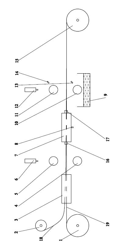
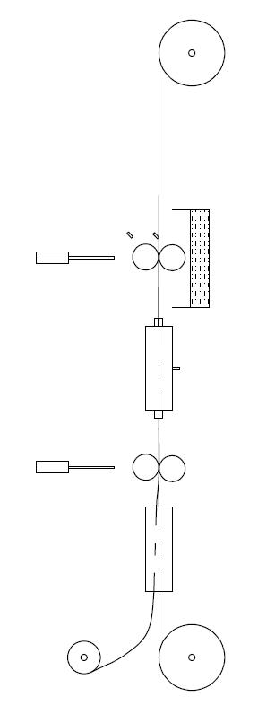
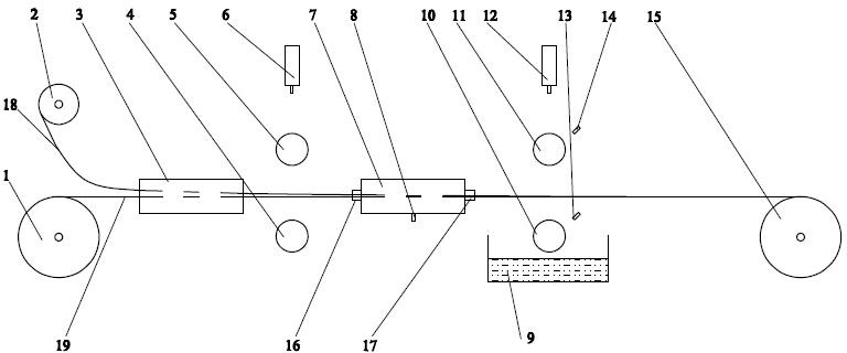
[0029] 1) First, according to the material properties and dimensions of the solder strip 18 and the contact strip 19, different front and rear roller electrode pairs (4, 5, 10, 11) are made;

[0030] 2) The strips (18, 19) processed to the predetermined size are placed on the unwinding device (2, 1);

[0031] 3) The strips (18, 19) are treated with surface degreasing and surface inclusions through the strip surface treatment device 3;

[0032] 4) The re-solder equipment is closed and loosened, if attached figure 1 As shown, the strip passes through the front roller electrode pair (4, 5), the rear roller electrode pair (10, 11), the rear roller electrode pair cooling water (13, 14), and the air inlet 8 of the re-solder atmosphere protection device. is closed;

[0033] 5) Press the strip (18, 19) onto the lower roller electrode (4, 10) through the upper roller el...

Embodiment 1

[0040] The contact material is AgCdO12, and the cross-section of the strip is 44mmX1mm; the solder strip is BCu80AgP, and the cross-section of the strip is 40X0.08mm. The specific re-soldering steps are as follows:

[0041] 1) Make copper-tungsten roller electrodes, and the front and rear roller electrodes have a uniform specification of Φ100mmX50mm;

[0042]2) The contact strip 19 is placed on the unwinding device 1, and the solder strip 18 is placed on the unwinding device 2;

[0043] 3) The strip (18, 19) passes through the strip surface treatment device 3, the front roller electrode pair (4, 5), the re-solder atmosphere protection device 7, the rear roller electrode pair (10, 11), and the strip surface treatment Device 3, cylinders (6, 12) for upper roller electrodes, air inlet 8 of re-solder atmosphere protection device, rear roller electrode pair (10, 11), and rear roller electrode pair cooling water (13, 14) are all closed and loose state;

[0044] 4) Press the strip ...

Embodiment 2

[0049] The contact material is AgSnO 2 (12), the strip cross-section specification is 52mmX1.8mm; the solder strip is BAg65CuP, and the strip section specification is 50X0.1mm. The specific re-solder steps are as follows:

[0050] 1) Make copper-tungsten roller electrodes, and the front and rear roller electrodes have a uniform specification of Φ300mmX60mm;

[0051] 2) The contact strip 19 is placed on the unwinding device 1, and the solder strip 18 is placed on the unwinding device 2;

[0052] 3) The strip (18, 19) passes through the strip surface treatment device 3, the front roller electrode pair (4, 5), the re-solder atmosphere protection device 7, the rear roller electrode pair (10, 11), and the strip surface treatment Device 3, cylinders (6, 12) for upper roller electrodes, air inlet 8 of re-solder atmosphere protection device, rear roller electrode pair (10, 11), and rear roller electrode pair cooling water (13, 14) are all closed and loose state;

[0053] 4) Press t...


PUM


Abstract

The invention discloses special equipment and preparation method of a contact strip compound solder for a low-voltage appliance. The equipment consists of mechanisms, such as a contact strip unwrapping device, a compound solder contact strip wrapping device, a solder strip unwrapping device, a strip surface processing device, strip heating front-roller wheel electrode pairs, a compound solder atmosphere protective tube, strip heating back-rolling wheel electrode pairs and the like. The invention has the advantages of high speed of contact strip compound solder, high utilization ratio of energy sources, even and stable solder layers and low contact resistance of a solder layer and a contact layer.

Description

technical field [0001] The invention relates to a special equipment for re-soldering contact strips for low-voltage electrical appliances, and a manufacturing method for using the equipment to manufacture re-soldered contact strips. Background technique [0002] In the welding process of sheet contacts for low-voltage electrical appliances, the brazing process is often used for welding, and sheet solder needs to be added to the contacts. Whether the process of adding solder is manual welding or automatic welding, there are unstable and complicated solder additions. Problems, thus greatly reducing production efficiency, and welding quality also has great fluctuations. At the same time, some points on the market are produced by single-point re-soldering in the furnace. The re-solder contacts prepared by this method have uneven solder layer thickness and uneven solder spreading. At the same time, there is a high-temperature stage in the re-soldering process. During the process...

Claims


Application Information

Patent Timeline
IPC IPC(8): B23K3/00B23K3/08B23K1/20
Inventor 刘立强谢继峰郑宁柏小平翁桅
Owner ZHEJIANG FUDA ALLOY MATERIALS TECH CO LTD
Why Eureka
Try Eureka