
Non-contact-type ultrasonic-assisted laser welding method

An auxiliary laser, non-contact technology, used in laser welding equipment, welding equipment, metal processing equipment, etc., can solve the problems of joint softening, easy generation of pores, thermal cracks, etc., to avoid pores, improve efficiency, and improve mechanical properties. Effect

Inactive Publication Date: 2011-05-18
HARBIN INST OF TECH
View PDF11 Cites 33 Cited by
  • Summary
  • Abstract
  • Description
  • Claims
  • Application Information

AI Technical Summary

Problems solved by technology

[0005] The present invention solves the technical problems such as air holes, thermal cracks, and joint softening that occur in existing laser welding titanium alloys, aluminum alloys and other metals; and provides an ultrasonic non-contact auxiliary laser welding method

Method used


Image

  • Non-contact-type ultrasonic-assisted laser welding method
  • Non-contact-type ultrasonic-assisted laser welding method
  • Non-contact-type ultrasonic-assisted laser welding method

Examples


specific Embodiment approach 1

[0013] Specific embodiment one: the method for ultrasonic non-contact assisted laser welding in this embodiment is carried out according to the following steps:

[0014] 1. Treat the surface of the metal workpiece to be welded until the bright metal color is exposed on the surface to be welded. The metal workpiece to be welded is titanium alloy or aluminum alloy;

[0015] 2. Carry out the joint connection of the metal workpiece to be welded which has been processed in step 1, and rigidly fix it;

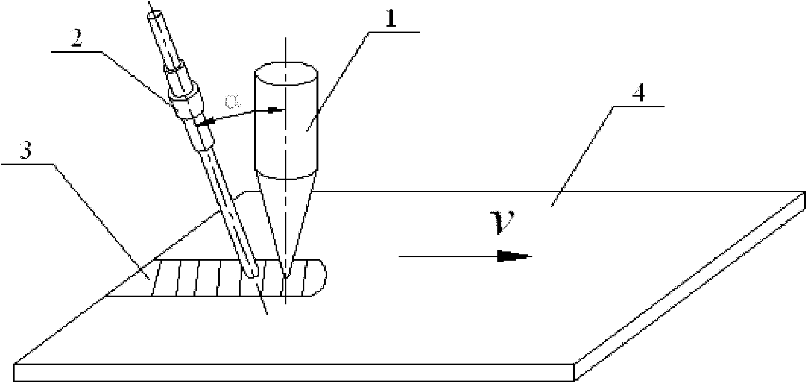
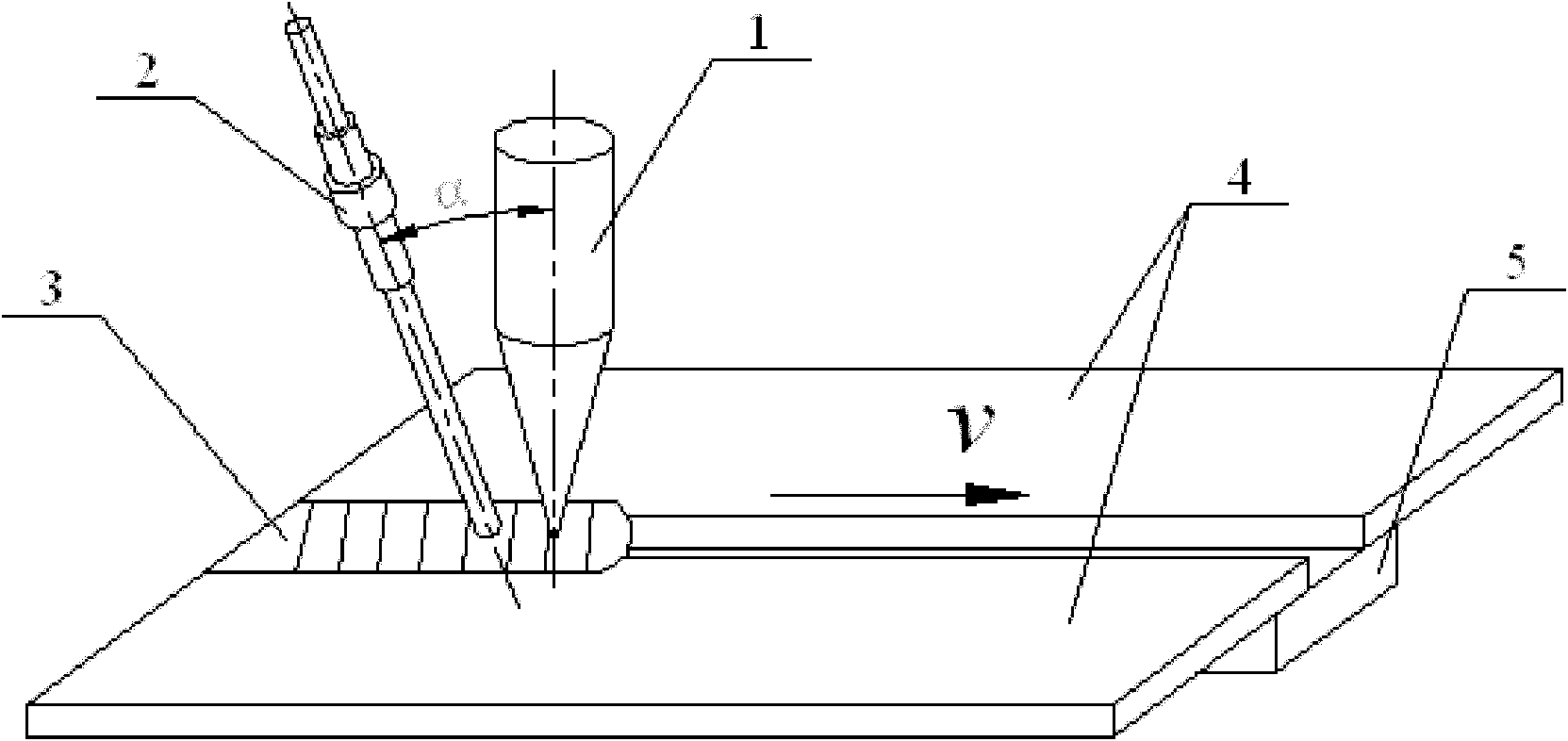
[0016] 3. Then use argon as protective gas, CO 2 The laser is used as a laser source for laser welding, and ultrasonic waves are applied to the molten pool generated by laser welding during the welding process. The ultrasonic waves are generated by a power ultrasonic generator placed in the air, and the lowest end of the ultrasonic horn of the ultrasonic generator does not touch The metal workpiece to be welded, and the ultrasonic horn of the ultrasonic generating device is inclined...

specific Embodiment approach 2

[0017] Embodiment 2: This embodiment differs from Embodiment 1 in that: the joint connection method described in step 2 is lap joint or deep penetration welding. Other steps and parameters are the same as in the first embodiment.

specific Embodiment approach 3

[0018] Embodiment 3: The difference between this embodiment and Embodiment 1 or 2 is that the angle a between the ultrasonic horn of the ultrasonic generating device and the laser beam in step 3 is 35°-55°. Other steps and parameters are the same as those in Embodiment 1 or Embodiment 2.


PUM

PropertyMeasurementUnit
Thicknessaaaaaaaaaa

Abstract

The invention relates to a non-contact-type ultrasonic-assisted laser welding method belonging to the field of material processing engineering and aiming at solving the technical problems of easy air hole and hot crack generation, joint softening, and the like occurring in the laser welding of metal, such as titanium alloys, aluminum alloys, and the like in the prior art. The invention adopts non-contact-type ultrasonic-assisted laser welding of titanium alloys or aluminum alloys, the generated cavitation action and the breaking theory of ultrasonic waves in a molten pool can be used for thinning grains of a welding line and further improving the mechanical performance of the welding line; the high-frequency vibration of the ultrasonic waves can generate a certain stirring action in the molten pool, and moreover, the ultrasonic waves per se have cavitation action, and thus, the full overflow of gases in the liquid metals and the reduction or avoidance of the generation of air holes are benefited. Compared with contact-type ultrasonic-assisted welding, the method has a wide use range because an ultrasonic tool head is not in contact with a workpiece, is convenient to realize omnidirectional automatic flexible welding and improves the efficiency.

Description

technical field [0001] The invention belongs to the field of material processing engineering, and in particular relates to an ultrasonic non-contact assisted laser welding method. Background technique [0002] Non-ferrous metals such as titanium alloys and aluminum alloys are currently the most widely used metal structural materials in the industry, and have been widely used in aviation, aerospace, automobiles, machinery manufacturing, shipbuilding and chemical industries. With the rapid development of science and technology and industrial economy in recent years, the demand for welded structural parts of this material is increasing, and the research on its weldability is also in-depth. [0003] Laser welding technology was developed in the 1970s and gained widespread attention in Europe, the United States, and Japan in the 1980s. It uses the ultra-high power density of the laser as a welding heat source to melt the base metal to realize the connection. It has the advantage...

Claims


Application Information

Patent Timeline
IPC IPC(8): B23K26/20B23K26/32B23K26/42B23K26/21B23K26/60
Inventor 雷正龙陈彦宾马轶男
Owner HARBIN INST OF TECH
Learn More