Method and device for strengthening fastening hole by shocking with ring laser

A technology of laser shock strengthening and fastening holes, which is applied in the direction of heat treatment equipment, furnaces, heat treatment furnaces, etc., can solve the problems of unfavorable continuous operation, small impact force of hole wall, and increased surface roughness of materials, etc., to achieve the benefit of continuous operation , Improve fatigue life, not easily damaged

Inactive Publication Date: 2011-05-18
JIANGSU UNIV
View PDF4 Cites 22 Cited by
  • Summary
  • Abstract
  • Description
  • Claims
  • Application Information

AI Technical Summary

Problems solved by technology

People such as Peter A. Simeone and Apostolos P. karafillis of U.S. General Company declared that the patent No. is the U.S. patent of US 6189356 B1, and the name is called shot peening method and device (Method and Apparatus for Peening), and this patent will be the cone surface The splitter rod extends into one end of the fastening hole, and the pellets are sprayed into the other end of the fastening hole. The inner wall of the fastening hole is shot peened by the conical reflection of the splitter rod, but it leads to an increase in the surface roughness of the material. Will offset the contribution of residual stress to prolong fatigue life to some extent
The Chinese patent No. 200610096476.5 filed by Zhang Yongkang, Zhang Xingquan and others is called a method and device for strengthening the hole wall based on laser shock wave technology. The patent uses laser shock waves to strengthen the inner wall of the hole, and the reflection surface for generating shock waves is a cone. surface, and the spot of the laser pulse used is a circular general spot. Since the fastening hole is small, the diameter of the laser pulse spot is also very small. The focused laser pulse is very easy to act on the tip of the cone, and the stress on the tip is concentrated. More serious, easy to damage, not conducive to continuous operation, and at the same time, the impact force on the hole wall is small, and the strengthening effect is not ideal

Method used


Image

  • Method and device for strengthening fastening hole by shocking with ring laser
  • Method and device for strengthening fastening hole by shocking with ring laser
  • Method and device for strengthening fastening hole by shocking with ring laser

Examples


Embodiment Construction

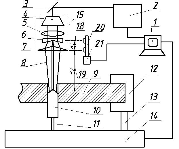
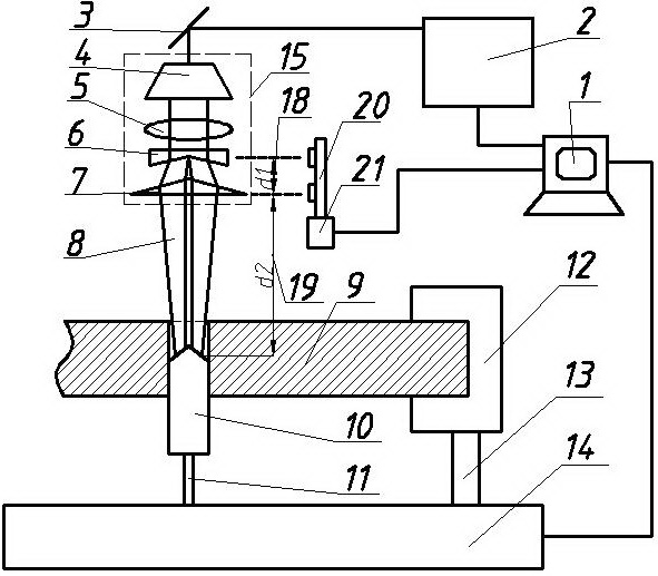
[0022] The details and working conditions of the specific device proposed by the present invention will be described in detail below in conjunction with the figures.

[0023] The laser shock strengthening device for fastening holes of the present invention includes: computer 1, high-power pulse laser 2, 45° total reflection mirror 3, spot adjustment device 15, energy absorption rod 10, feed mechanism A11, clamp 12, feed Mechanism B13, workbench 14, guide rail 20, stepping motor 21, water spray device; Described spot adjusting device 15 comprises: beam expander mirror 4, converging lens 5, conical lens A6, conical lens B7; Spot adjusting device 15 is located at Directly above the workbench 14, the feed mechanism A11 is set in the middle of the workbench 14, and the feed mechanism B13 is set on one side of the workbench 14. The feed mechanism A11 and the feed mechanism B13 are provided with clamps, and the energy absorption rod 10 is installed on the feeder. On the fixture for t...


PUM


Abstract

The invention discloses a method and device for strengthening a fastening hole by shocking with ring laser, relating to the technical field of machining and manufacturing of fastening holes. In the invention, the head part of an energy absorbing rod (10) is a conical surface; high power pulse laser outputs ring laser pulse (8) through a spot adjusting device (15); the ring laser pulse (8) accommodates the tip of the conical head surface of the energy absorbing rod (10) in a hollow part of a laser beam; and the ring laser pulse (8) acts on the conical head surface of the energy absorbing rod (10) to induce a plasma (17) to explode so as to generate shock waves acted on the inner wall of the fastening hole, and thereby the fastening hole is strengthened. The method and the device are suitable for strengthening the fastening hole with a small diameter; the hollow part of the ring laser pulse (8) keeps away from the tip of the conical surface of the energy absorbing rod (10) so that the energy absorbing rod (10) is difficult to be damaged, which is favorable for continuous operation, and the strengthening effect is good.

Description

technical field [0001] The invention relates to the technical field of fastening hole processing and manufacturing, in particular to a method and device for ring-shaped laser shock strengthening fastening holes, and is especially suitable for strengthening the inner surface of small-diameter fastening holes with severe stress concentration. technical background [0002] Fastening holes are typical stress concentration details on aircraft components, which are prone to fatigue cracks under the action of alternating loads, which will greatly reduce the safety, reliability and service life of the whole machine. Therefore, in design, material selection and manufacturing, how to reduce the influence of stress concentration in fastening holes as much as possible, improve the fatigue resistance of aircraft structures, prolong the service life, and ensure the reliability and safety of aircraft structures is an important aspect of design and material research. important research topi...

Claims


Application Information

Patent Timeline
Patent Type & Authority Applications(China)
IPC IPC(8): C21D1/09C21D9/00
Inventor 姜银方张永康钱晓明管海兵张朝阳
Owner JIANGSU UNIV
Why Eureka
Try Eureka