
Modular generation method for multi-waveform radar signal

A technology of radar signal and generation method, applied in the field of radar frequency synthesis, can solve the problems of cumbersome process, difficulty, occupation of developers' energy, etc., to achieve the effect of improving development speed, good versatility and shortening development cycle

Inactive Publication Date: 2011-05-25
中国兵器工业第二〇六研究所
View PDF1 Cites 39 Cited by
  • Summary
  • Abstract
  • Description
  • Claims
  • Application Information

AI Technical Summary

Problems solved by technology

[0004] But in the current design, first of all, the control software design for different chips takes up a lot of energy of the developers, and for the same chip, different developers adopt various development methods and compile various programs, but the actual work results are different. This undoubtedly leads to repeated development and waste of human resources, and also makes it extremely difficult to shorten the R&D cycle
Secondly, the design and generation of various waveform signals requires the writing, debugging, and repeated downloading and burning of different FPGA programs. The process is very cumbersome and time-consuming.

Method used


Image

  • Modular generation method for multi-waveform radar signal
  • Modular generation method for multi-waveform radar signal
  • Modular generation method for multi-waveform radar signal

Examples


Embodiment Construction

[0033] Taking the application of modular software in AD9957 as an example, the specific implementation of the multi-waveform radar signal modular generation method is introduced below.

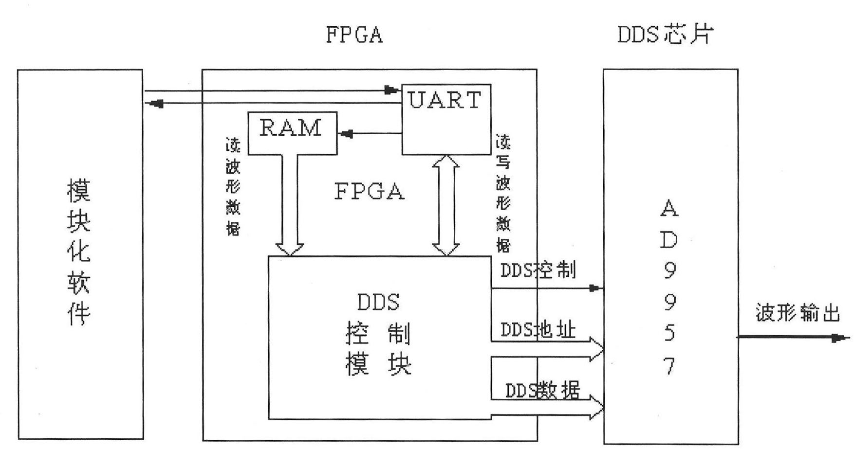
[0034] The overall structure of the multi-waveform radar signal module of the present invention is as follows: figure 1 As shown, it is composed of modular software, FPGA and DDS chip. The functions of each part are as follows:

[0035] 1. Modular software includes two parts: human-computer interaction interface and modular serial port timing.

[0036] 1.1 Human-computer interaction interface

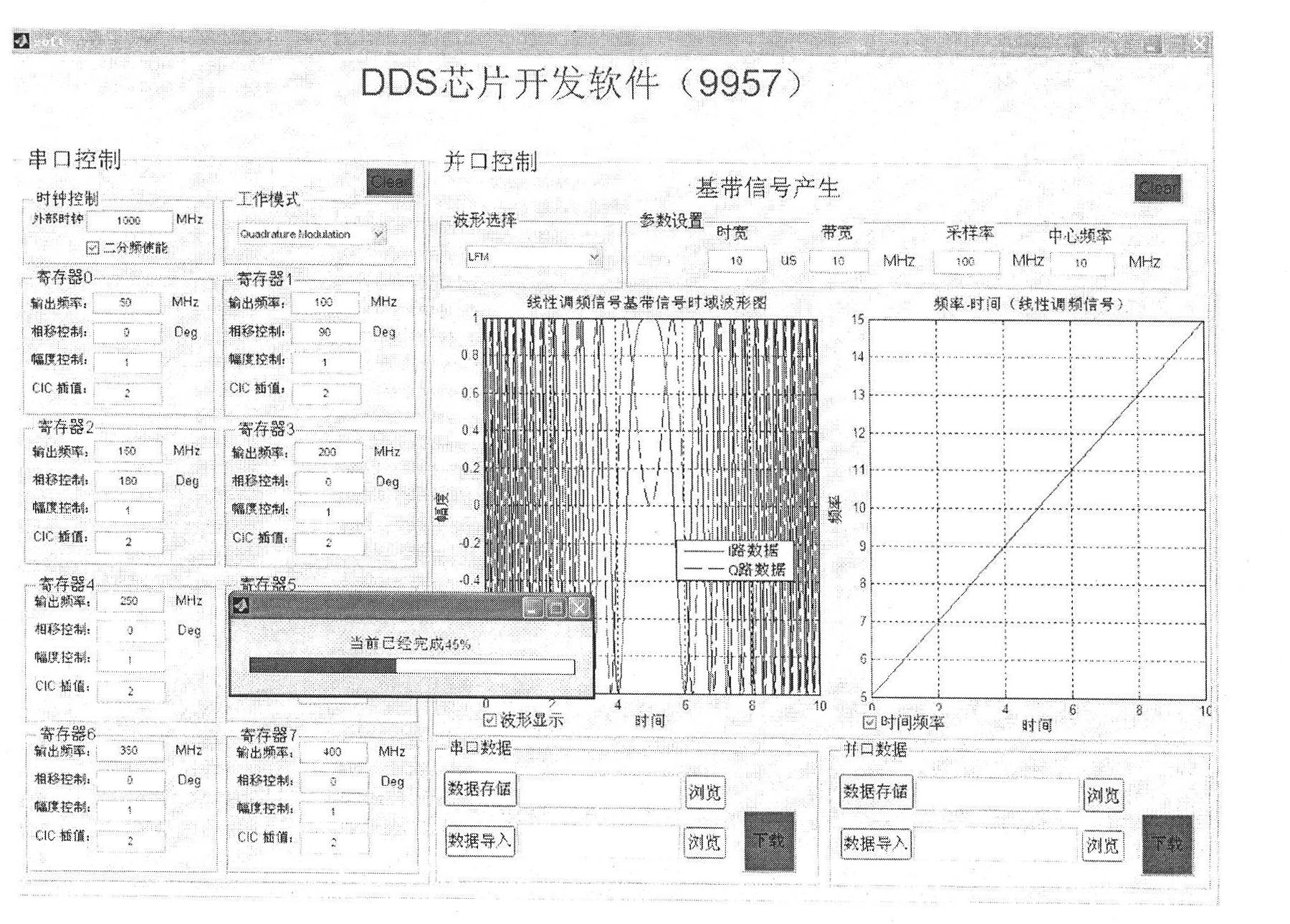
[0037] figure 2 Shown is the application of modularized software written by the present invention in AD9957, based on the software operation interface developed by MATLAB GUI technology. The software interface is divided into three parts: serial port control, parallel port control and serial and parallel port data control. The functions of each part are as follows:

[0038] 1.1.1 Serial port contro...


PUM


Abstract

The invention relates to a modular generation method for a multi-waveform radar signal, which belongs to the technical field of radar frequency synthesis and is applied to the design of a direct digital frequency synthesis (DDS)-based frequency synthesizer. A multi-waveform radar signal module consists of modular software, a field programmable gate array (FPGA) and DDS chips. The modular software comprises a man-machine interactive interface and a modular serial port timing module, wherein the man-machine interactive interface performs relevant operation and storage of control parameters and waveform data of the DDS chips and performs data communication with the FPGA; and the modular serial port timing module generates modular serial port control timing which is suitable for the DDS series chips and completes data acquisition and updating by computer communication. The FPGA is provided with a random-access memory (RAM), a universal asynchronous receiver / transmitter (UART) and a DDS control module, and realizes the functions of data communication with a computer and the storage of the control parameters and waveform data of the DDS chips and DDS chip control. The DDS chips output various signals set by the parameters under the control of the FPGA. The modular software developed by the method configures different DDS chips, so various radar signals of point frequency, linear frequency modulation, nonlinear frequency modulation and phase encoding can be generated, and the software supports on-line programming and the real-time updating of the control parameters and waveform data of the DDS chips.

Description

technical field [0001] The invention relates to the technical field of radar frequency synthesis, and is applied in the design of a frequency synthesizer based on DDS (Direct Digital Frequency Synthesis) technology. The method adopts self-developed modular software to configure different DDS chips, and can quickly realize point frequency , linear frequency modulation, nonlinear frequency modulation and phase coding and other radar signal generation. Background technique [0002] With the emergence of radar in the 1930s and its large-scale application in the military field, waveform generation has always been an important research content in the field of radar. With the rapid development of modern digital technology and large-scale integrated circuit technology, waveform synthesis has developed from the traditional pure analog method to the current direct digital synthesis. The waveform generated by the digital method has strict coherence, repeatability, high stability and pr...

Claims


Application Information

Patent Timeline
IPC IPC(8): G01S7/02
Inventor 张春荣李辉王栋曹义余铁军
Owner 中国兵器工业第二〇六研究所
Learn More