
Short circuit-proof electric heating laminating machine

A laminator and electric heating technology, applied in lamination, lamination devices, layered products, etc., can solve problems such as combustion or deflagration of heat transfer oil, potential safety hazards, poor temperature control accuracy, etc., and prolong the service life , Reduce maintenance rate, improve production efficiency

Inactive Publication Date: 2011-06-08
SHANGHAI SHENKE TECH
View PDF0 Cites 5 Cited by
  • Summary
  • Abstract
  • Description
  • Claims
  • Application Information

AI Technical Summary

Problems solved by technology

The use of oil heating has the advantages of uniform heating, large-area temperature uniformity, accurate temperature adjustment and temperature control, and can ensure that the temperature difference is controlled within plus or minus 2 degrees Celsius within 100 mm of the edge. It has the advantages of good heat transfer effect and convenient operation. However, there is a relatively obvious defect in heating with heat transfer oil, that is, in the case of system leakage caused by an accident, the heat transfer oil may burn or deflagrate when it meets an open flame, causing a greater safety hazard; The heating method heats the heated body. Although the safety performance is good, compared with the oil heating method, the traditional electric heating method is difficult to achieve temperature uniformity in a large area, and the temperature control accuracy is not good. When solar cell modules are laminated, the quality of finished products of solar cell modules is often affected by the uneven heating of the components as a whole.

Method used


Image

  • Short circuit-proof electric heating laminating machine
  • Short circuit-proof electric heating laminating machine
  • Short circuit-proof electric heating laminating machine

Examples


Embodiment Construction

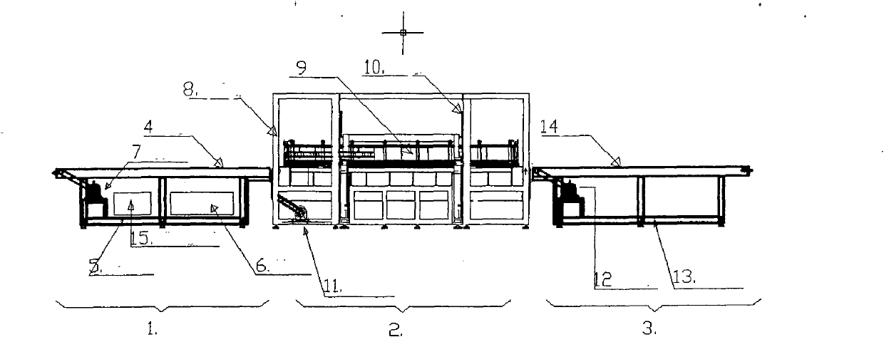
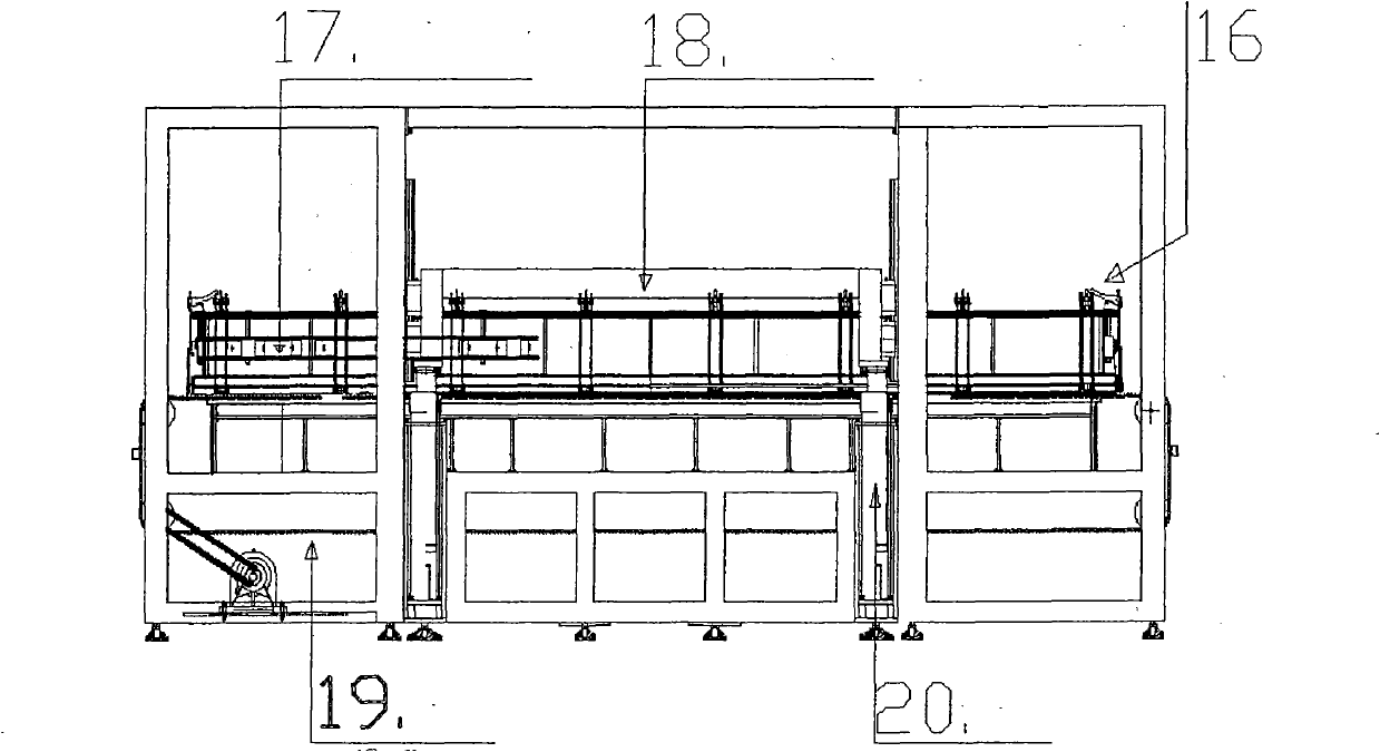
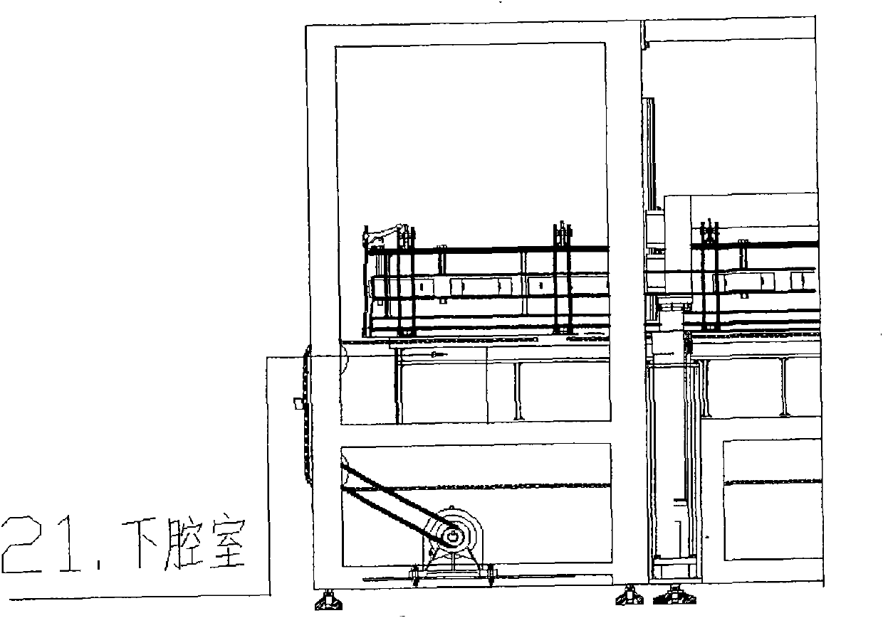
[0017] The following is a specific introduction to the new electric heating laminator: such as ( figure 1 ) is the general assembly drawing of the new type electric heating laminator, where Figure (2) is an enlarged view of the lamination section in Figure (1), and Figure (3) is a partial view of Figure (2), mainly showing the lower chamber.

[0018] As shown in Figure (1), the new electric heating laminator is mainly composed of three sections, namely the feeding table 1, the laminating section 2, and the discharging table 3.

[0019] The function of the feeding platform is to place the installed solar cell components flatly on the feeding platform in advance. Feeding table: feeding table support frame 5 It constitutes the main frame of the feeding table and the control system 6 , thyristor and transformer 15 , feed motor 7 Usually installed inside it. Control System 6 , is the core part of the laminator used to control the mechanical movement and lamination process. S...


PUM


Abstract

The invention relates to a short circuit-proof electric heating laminating machine, which comprises a heating workbench and an upper cover, wherein the upper cover is formed by combining an upper box chamber, a silica gel plate and an upper chamber sealing ring in turn, wherein a laid battery component is arranged on the workbench top of the laminating machine, the upper cover is pressed down to be tightly combined with the edge of the heating workbench and a vacuum chamber is formed between the upper cover and the heating workbench. A lower chamber sealing ring is arranged on the periphery of the heating workbench to seal the vacuum chamber. A heater and a temperature controller are also arranged in the heating workbench, a disc which is made of a steel plate and has a spring is laid below the heater, and an aluminum silicate light brick, which is as large as the heating plate and some 5 centimeters thick and is covered by tetrafluoride cloth, is arranged below the disc. The heater is positioned between the heating plate and the aluminum silicate light brick, a lead of the heater is welded with a small section of copper wire and connected with a screw of a bakelite plate, and the screw is communicated with the outside. In the invention, the control mode of the electric heater is primarily described, a primary coil of a transformer is controlled by a silicon-controlled solid-state relay, and the heater is connected with the secondary coil of the transformer, so short circuit of the heater under vacuum is voided effectively, the repair rate of device is greatly reduced, the service life of the device is prolonged, and the heater is suitable to be applied to the electric heating laminating machine for use in a solar battery assembly process.

Description

technical field [0001] The invention relates to equipment in the production process of solar battery components, in particular to a hot plate uniform heating lamination machine suitable for the solar battery assembly process. Background technique [0002] With the rapid development of the economy and the continuous advancement of science and technology, the consumption and demand for energy in social life has also increased sharply. At present, most of the energy widely used by human beings is still fossil energy represented by coal and oil. Since the development of fossil energy, although its exploitation and use technology has been very mature, the accompanying problems cannot be ignored. First of all, fossil energy is a non-renewable resource, and its total storage must be an irreversible process of continuous reduction; second, the use of fossil energy will produce a lot of pollution, and the carbon dioxide, sulfur dioxide and nitrogen base produced during the combustio...

Claims


Application Information

Patent Timeline
Patent Type & Authority Applications(China)
IPC IPC(8): B32B37/06
Inventor 傅家勤
Owner SHANGHAI SHENKE TECH
Learn More