Centrifugal efficient wood chip granulator

A technology of pellet mill and sawdust, which is applied in the direction of manufacturing tools and wood processing appliances, etc., can solve the problems that the compression chamber cannot dissipate heat in time, reduce the service life of the whole machine, and feed uneven materials, so as to reduce equipment maintenance costs and prolong service life. , Guarantee the effect of forming rate

Active Publication Date: 2011-06-15
山东宇龙机械有限公司
View PDF6 Cites 4 Cited by
  • Summary
  • Abstract
  • Description
  • Claims
  • Application Information

AI Technical Summary

Problems solved by technology

[0006] ①Due to the layout of the ring die, the feed port of the ring die granulator must be placed on the side, and a forced thrust device is required to fill the ring die. Even so, it is still difficult for materials with light specific gravity to enter the compression chamber;
[0007]②The layout of the ring die causes the compression cavity to not dissipate heat in time, which reduces the service life of the whole machine;
[0008] ③When the ring die rotates, the material in the compression chamber is prone to arching, resulting in uneven feeding, which affects the output and compression efficiency; at the same time, the ring die rotates, and the material has no centrifugal force at all, resulting in uneven distribution of the material
[0009] ④The ring die and the pressure roller need to be driven by independent drive motors respectively, which consumes a lot of power and increases the difficulty and cost of manufacturing

Method used


Image

  • Centrifugal efficient wood chip granulator
  • Centrifugal efficient wood chip granulator
  • Centrifugal efficient wood chip granulator

Examples


Embodiment 1

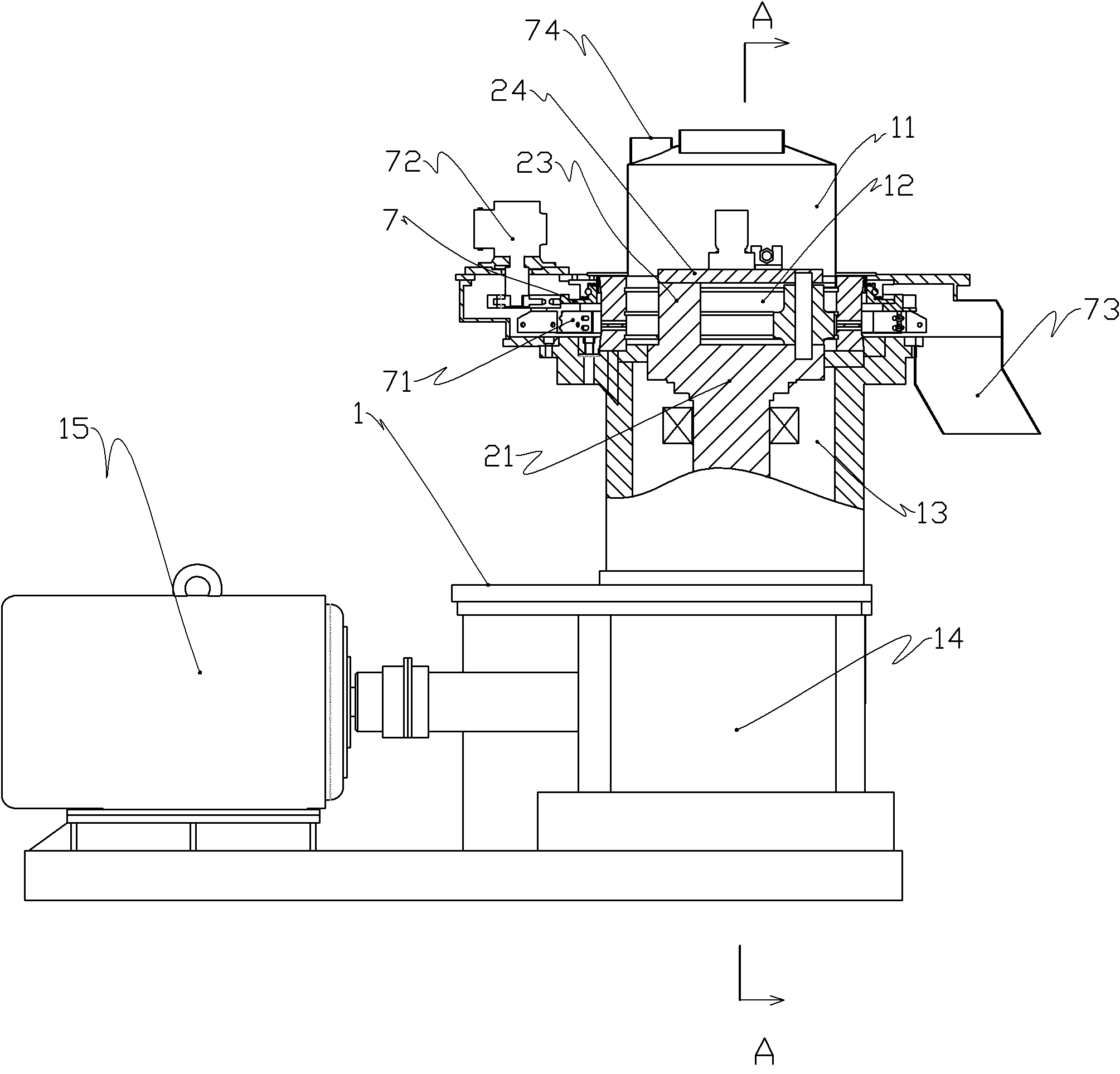
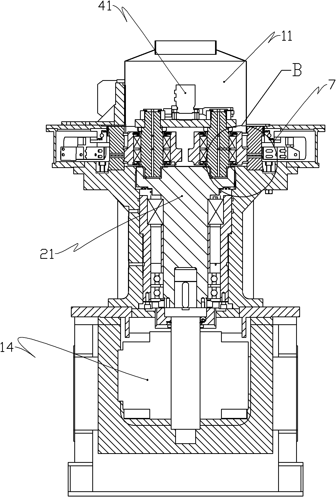
[0039] Such as Figure 1 to Figure 6 As shown, this kind of centrifugal high-efficiency sawdust granulator includes a cast-molded frame 1, which is divided into upper, middle, and lower parts. It is a rotating spindle power transmission mechanism. A speed reducer 14 is installed at the bottom of the frame, and the power input shaft of the speed reducer 14 is connected to the motor 15. The power output shaft and the input shaft of the speed reducer used in this place are arranged at 90 degrees, and the power output shaft of the speed reducer 14 is connected to the The rotating main shaft 21 is vertically installed on the frame 1, the rotating main shaft 21 is located on the top of the reducer 14, and the journals at both ends of the rotating main shaft are provided with bearings, and a lubrication system is designed at the bearing, that is, designed in the This is achieved by the first oil circuit supplying oil to the rotating spindle bearings.

[0040]The lower end surface o...

Embodiment 2

[0050] Such as Figure 7 , Figure 8 As shown, the difference from Embodiment 1 is that the pressure roller adjustment mechanism is hydraulic automatic adjustment, and the pressure roller adjustment mechanism includes a drive shaft 81 installed on the upper end surface of the rotating main shaft 21, and a swinging shaft is fixedly installed on the upper end of the drive shaft 81. Rod 82, the swing rod 82 is driven by the first oil cylinder 83 installed on the support plate; a main gear 84 is fixedly installed on the drive shaft 81, and the main gear 84 is respectively meshed with the slave gear 85 installed on the pinch wheel shaft 31, through The oil cylinder drives the main gear to achieve the purpose of adjusting the spatial positions of the three pressure rollers.

[0051] Teeth are provided on the outside of the swing rod 82, and the swing rod can realize the locking function under the control of the locking mechanism 86, so as to prevent the space position of the pressu...


PUM


Abstract

The invention provides a centrifugal efficient wood chip granulator which is granule manufacture equipment. The granulator comprises a frame, a die which is statically fixed on the frame, a rotating main shaft connected with a power mechanism and a pinch roller assembly arranged on the rotating main shaft, wherein a pinch roller adjusting device on the pinch roller assembly can ensure that the pinch roller and the inner surface of the die are constantly inscribed. Wood chips and other materials are fed from the upper end of the granulator, thus a static granulating mode of the die is created, and the materials in a compression cavity are ensured to be in a compressed and centrifuged state, so the granulation effect is good; axes of the die and rotating main shaft are superposed and in a vertical state, the die has a unique design, and the treatment efficiency and the treatment effect are improved.

Description

technical field [0001] The invention relates to a particle manufacturing equipment, in particular to a centrifugal high-efficiency sawdust granulator which utilizes wood chips and other plant fibers to make fuel particles. Background technique [0002] Renewable biofuels refer to high-density fuel rods or pellets formed by compressing agricultural and forestry wastes such as straw, sawdust, weeds, shrub branches and even fruit shells and peels at room temperature or high temperature. The combustion value of this particle is 4 times higher than the combustion value of the traditional combustion method. It is a high-grade clean energy with a combustion method and calorific value close to coal but basically no pollutant emissions. It is used for urban and rural domestic energy and industrial use. It can provide an environmentally friendly, economical and safe green consumption method, and is a new energy advocated by the state. [0003] Worldwide, the bottleneck of biofuel app...

Claims


Application Information

Patent Timeline
IPC IPC(8): B27L11/06
Inventor 郭成军
Owner 山东宇龙机械有限公司
Why Eureka
Try Eureka