Multilayer piezoelectric element, injection device using same and fuel injection system

A piezoelectric element and injection device technology, which is applied in the manufacture/assembly of piezoelectric/electrostrictive devices, charging systems, fuel injection devices, etc., can solve the problems of reduced displacement characteristics, peeling of conductive parts, thermal damage, etc. Achieves the effects of improved heat dissipation characteristics, improved bonding strength, and increased surface area

Inactive Publication Date: 2011-07-20
KYOCERA CORP
View PDF5 Cites 2 Cited by
  • Summary
  • Abstract
  • Description
  • Claims
  • Application Information

AI Technical Summary

Problems solved by technology

[0005] However, when the multilayer piezoelectric element using the external electrodes described in Patent Document 1 is used under severe conditions such as high voltage, high pressure, or long-term continuous driving, the following problems may occur: connection The conductive member fixed to the external electrode peels off, so that the voltage cannot be supplied to the external electrode and the multi-layer piezoelectric element does not displace
[0006] Furthermore, when a multi-layer piezoelectric element is driven at high speed by passing a large current to the external electrodes, there is a problem that the external electrodes generate heat and cause thermal breakdown.
[0007] Or there is a problem that a part of the external electrode may be peeled off from the side of the laminated body, and a voltage cannot be supplied to the internal electrode layer of the laminated body, so that the initial displacement of the multi-layer piezoelectric element cannot be maintained.
That is, in the multi-layer piezoelectric element, when the high voltage is continuously driven for a long time, due to the stress generated at the joint interface between the side surface of the multi-layer body and the external electrode, a part of the external electrode is removed from the side surface of the multi-layer body Therefore, a voltage cannot be supplied from the external electrode to a part of the piezoelectric layer through the internal electrode layer, resulting in a decrease in displacement characteristics.

Method used


Image

  • Multilayer piezoelectric element, injection device using same and fuel injection system
  • Multilayer piezoelectric element, injection device using same and fuel injection system
  • Multilayer piezoelectric element, injection device using same and fuel injection system

Examples


no. 1 approach

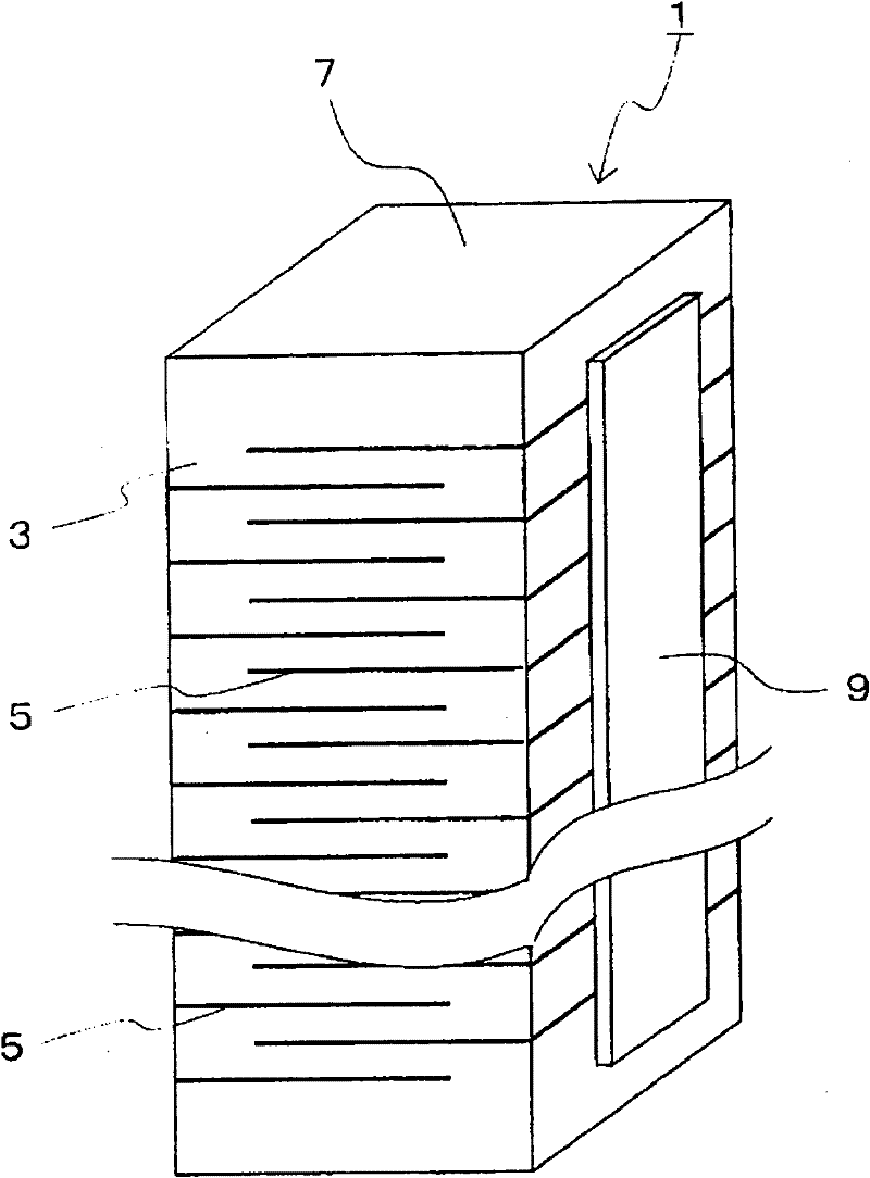
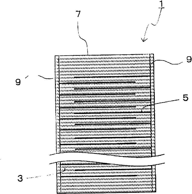
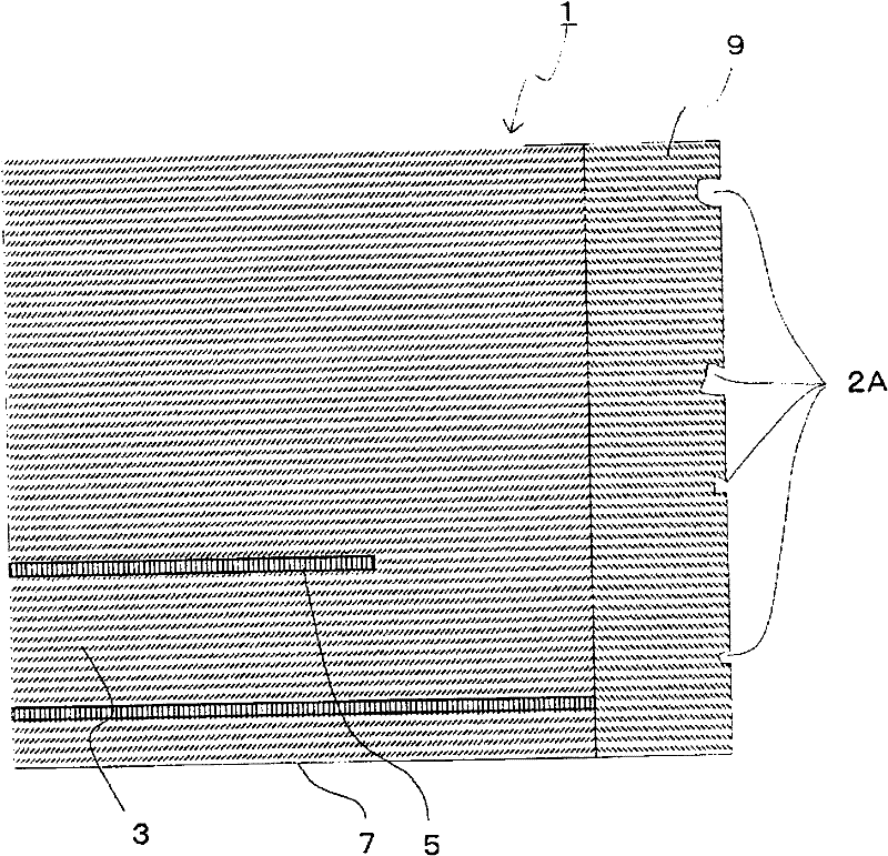
[0053] figure 1 is a perspective view showing an example of an embodiment of the first multi-layer piezoelectric element of the present invention, figure 2 yes figure 1 A cross-sectional view parallel to the stacking direction of the stacked piezoelectric element shown. image 3 yes figure 2 An example of an enlarged cross-sectional view of the vicinity of the bonding interface between the laminated body of the multi-layer piezoelectric element and the external electrodes shown.

[0054] Such as image 3 As shown, the multi-layer piezoelectric element 1 of the first embodiment includes: a laminate 7 in which piezoelectric layers 3 and internal electrode layers 5 are alternately laminated; A plurality of open pores 2A are formed on the surface of the external electrode 9 .

[0055] In this way, since a plurality of open pores 2A are formed on the surface of the external electrode 9, when using solder or a conductive adhesive to connect and fix conductive members (not sho...

no. 2 approach

[0072] figure 1 is a perspective view showing an example of an embodiment of the second multilayer piezoelectric element of the present invention, figure 2 yes figure 1 A cross-sectional view parallel to the stacking direction of the stacked piezoelectric element shown. in addition, Figure 10 yes figure 2 An example of an enlarged cross-sectional view of the vicinity of the bonding interface between the laminated body of the multi-layer piezoelectric element and the external electrodes shown.

[0073] Such as Figure 10 As shown, the second multi-layer piezoelectric element 1 of the present invention includes: a laminate 7 in which piezoelectric layers 3 and internal electrode layers 5 are alternately laminated; In the connected external electrode 9 , a plurality of pores 2B exist on the inner surface side of the external electrode 9 , that is, on the side opposite to the laminated body 7 .

[0074]In this way, since the plurality of pores 2B are located toward the su...

Embodiment

[0139]

[0140] A piezoelectric actuator having the first multi-layer piezoelectric element of the present invention was manufactured as follows. First, lead zirconate titanate (PbZrO 3 -PbTiO 3 ) is mainly composed of piezoelectric ceramic quasi-fired powder, binder, and plasticizer to prepare a slurry. Using this slurry, a ceramic green sheet constituting a piezoelectric layer having a thickness of 150 μm was produced by the doctor blade method.

[0141] In addition, a binder is added to a silver-palladium alloy to prepare a conductive paste constituting an internal electrode layer.

[0142] Next, a conductive paste to be an internal electrode layer was printed on one side of the ceramic green sheet by a screen printing method, and 300 ceramic green sheets on which the conductive paste was printed were laminated. Next, it bakes at 980-1100 degreeC, and obtains a laminated body.

[0143] After grinding the obtained laminate into a predetermined shape using a surface gri...


PUM


Abstract

The present invention provides a multilayer piezoelectric element having excellent durability, wherein a conductive member is not separated from an external electrode even when the element is continuously operated for a long time at high electric field and high pressure. The multilayer piezoelectric element (1) comprises a laminate (7) wherein piezoelectric layers (3) and internal electrode layers (5) are alternately laminated, and an external electrode (9) which is bonded to a lateral surface of the laminate (7) and electrically connected to the internal electrode layers (5). The surface of the external electrode (9) is provided with a plurality of open pores (2). Due to the open pores (2), the bonding strength of the external electrode (9) to a conductive member is improved, thereby preventing separation of the conductive member. In addition, since the heat dissipation characteristics of the external electrode are improved, the external electrode can be prevented from a thermal breakdown due to heat generation.

Description

technical field [0001] The present invention relates to a multilayer piezoelectric element used for, for example, a drive element (piezoelectric actuator), a sensor element, a circuit element, and the like. As the driving element, for example, a fuel injection device of a motor vehicle engine, a liquid injection device such as an inkjet head, a precision positioning device such as an optical device, and an anti-vibration device are exemplified. As the sensor element, for example, a combustion pressure sensor, a knock sensor, an acceleration sensor, a load sensor, an ultrasonic sensor, a pressure sensitive sensor, and a yaw rate sensor are exemplified. Moreover, as a circuit element, a piezoelectric gyroscope, a piezoelectric switch, a piezoelectric transformer, and a piezoelectric circuit breaker are mentioned, for example. Background technique [0002] As an external electrode in a conventional multilayer piezoelectric element, as disclosed in Patent Document 1, a conducti...

Claims


Application Information

Patent Timeline
Patent Type & Authority Applications(China)
IPC IPC(8): H01L41/083F02M51/06H01L41/187H01L41/22H02N2/00H01L41/293
CPCH01L41/0472H01L41/047H01L41/293H01L41/083H10N30/872H10N30/063
Inventor 中村成信
Owner KYOCERA CORP
Why Eureka
Try Eureka