Flying-shear main-transmission gearwheel steel and preparation method thereof

A manufacturing method and a main transmission technology, applied in the field of rolling machinery, can solve the problems of difficulty in ensuring the uniformity of the hardened layer of the tooth surface, affecting the contact fatigue performance of the tooth surface, affecting the machining accuracy of the tooth shape, etc., so as to reduce harmful inclusions, The effect of avoiding tooth flank failure and improving load-carrying capacity and reliability

Active Publication Date: 2011-08-24
BAOSHAN IRON & STEEL CO LTD
View PDF12 Cites 46 Cited by
  • Summary
  • Abstract
  • Description
  • Claims
  • Application Information

AI Technical Summary

Problems solved by technology

[0007] (1) There are welding residual stress and stress concentration in the welding part of the web, which may easily cause the web to crack
[0008] (2) The ring gear is a large-diameter thin-walled annular workpiece, which is prone to deformation during processing and affects the machining accuracy of the tooth shape
[0009] (3) Due to the limitations of the induction hardening process, it is difficult to ensure the uniformity of the hardened layer on the tooth surface of the large gear treated by induction hardening, which affects the contact fatigue performance of the tooth surface
[0010] (4) The large gear is welded together by hubs, spoke plates and ring gears of different steels. During overall carburizing and quenching, cracks in welds and other parts and gear distortion are likely to occur. Carburizing and quenching is carried out before tailor welding and grinding Tooth, tailor welding deformation and then grinding teeth will cause uneven carburized layer on the tooth surface, and post-welding stress relief annealing treatment will easily damage the carburized layer structure
This technology is not suitable for large gears with heavy loads and shock conditions

Method used


Image

  • Flying-shear main-transmission gearwheel steel and preparation method thereof
  • Flying-shear main-transmission gearwheel steel and preparation method thereof
  • Flying-shear main-transmission gearwheel steel and preparation method thereof

Examples


Embodiment Construction

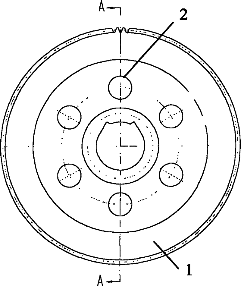
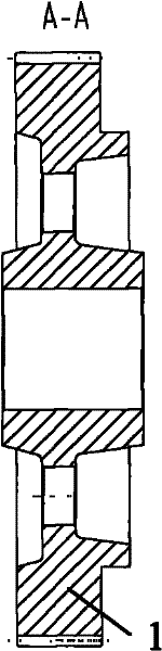
[0064] An existing bloom flying shear has been operating at full load under severe conditions such as high temperature, impact, and heavy load. The original 34Cr 2 Ni 2 Mo steel ring gear and No. 25 steel radial plate welded surface-hardened medium-hardened tooth surface (52-58HRC) large gear have been used for less than 2 years, and failure problems such as cracking at the welding part of the radial plate, severe wear and pitting of the tooth surface have occurred. Unable to continue using. In order to completely solve the problem of insufficient strength of the large gear and cracking of the welded part of the web, the large gear has been changed from the original welded structure to the integral structure.

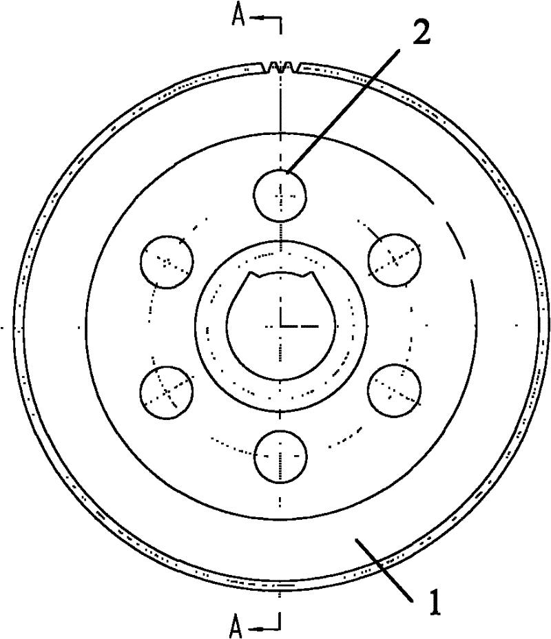
[0065] like figure 1 and figure 2 As shown, in order to reduce the weight of the large gear 1, the large gear adopts an inner concave structure, and six through holes 2 are processed along the circumferential direction of the gear in the inner recess; the inner hole...


PUM

PropertyMeasurementUnit
surface roughnessaaaaaaaaaa
reduction of areaaaaaaaaaaa
yield strengthaaaaaaaaaa

Abstract

The invention discloses a flying-shear main-transmission gearwheel steel and a preparation method thereof. The flying-shear main-transmission gearwheel steel comprises the following elements in percentage by mass: 0.10-0.20% of C, 2.00-3.00% of Cr, 2.50-3.50% of Ni, 0.4-1.00% of Mo, 0.10-0.40% of Si, 0.40-1.00% of Mn, at most 0.25% of Cu, at most 0.1% of Al, at most 0.020% of P, at most 0.015% ofS, at most 30ppm of O, at most 100ppm of N and at most 2ppm of H. The preparation method comprises the following steps: (1) smelting according to the percentage by mass to obtain a forging stock; (2)forging; (3) carrying out normalizing heat treatment; (4) carrying out gear hobbing; (5) carrying out surface carburization quenching heat treatment; and (6) carrying out gear grinding. The inventionenhances the bearing capacity and reliability of the gearwheel, and satisfies the production demands of high-carbon high-alloy steel and enhanced specifications, thereby having wide popularization and application prospects.

Description

technical field [0001] The invention belongs to the rolling machinery technology in the area of ​​bar steel and hot rolling, and relates to a gear manufacturing process, in particular to a flying shear main transmission large gear steel and a manufacturing method thereof. Background technique [0002] In areas such as bar steel and hot rolling, flying shears are important equipment for cutting the head, tail or segments of steel billets. The main transmission mechanism of flying shears is a key component for transmitting torque, realizing shear blade movement and shearing functions. The large gear is the core of the main transmission mechanism of the flying shear. In addition to meeting the requirements of heavy load, impact resistance, wear resistance, contact fatigue resistance and bending fatigue resistance, it also has strict requirements on the precision and stability of the transmission. [0003] At present, the start-stop four-link crank flying shear transmission mech...

Claims


Application Information

Patent Timeline
Patent Type & Authority Applications(China)
IPC IPC(8): C22C38/44C21D1/28C21D1/18C21D8/00
Inventor 孙大乐范群张健姚利松
Owner BAOSHAN IRON & STEEL CO LTD
Why Eureka
Try Eureka