Radiation-cured coatings
A radiation curing and coating technology, applied in coatings, devices for coating liquid on the surface, discharge tubes, etc., can solve the problems of increased uniformity and poor risk of damage along the coating, and achieve the goal of preventing delamination Effect
- Summary
- Abstract
- Description
- Claims
- Application Information
AI Technical Summary
Problems solved by technology
Method used
Image

Examples
example 1
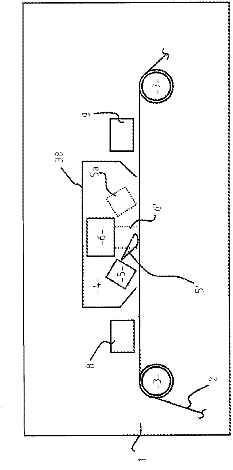
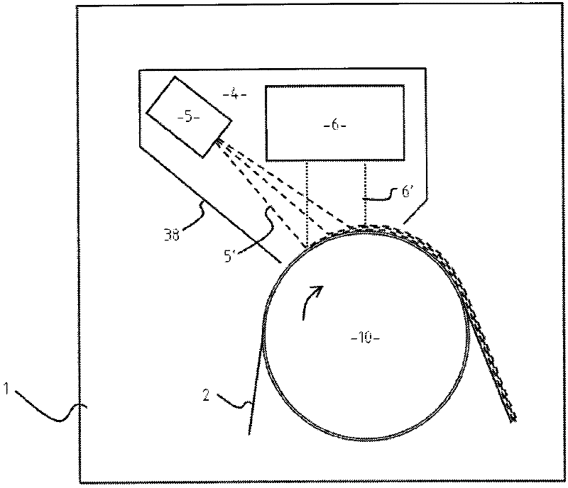
[0056] In this example, curing was performed using a flat-panel magnetron low-pressure plasma source consisting of an Edwards 75mm flat-panel magnetron and an MDX DC power supply; the acrylate transport source was located between the plasma source and the substrate in the process volume, and This transport leaves the plasma source towards the substrate. The acrylate used was tripropylene glycol diacrylate TRPGDA. For deposition and curing, the substrate is static. A heated single-hole precursor transfer tube as Figure 5a , the way of 5b is arranged before the source towards the substrate. The tube was heated for 8 minutes using a variable heating power supply (pulse space modulation, 10% duty cycle) at 200 watts at 240 volts. Cathode uses 6x10 -2 mbar residual ambient air at 200mA operated in constant current mode. 8 ml of material was delivered in 3 seconds and the resulting substrate was coated with cured acrylate with very good adhesion.
example 2
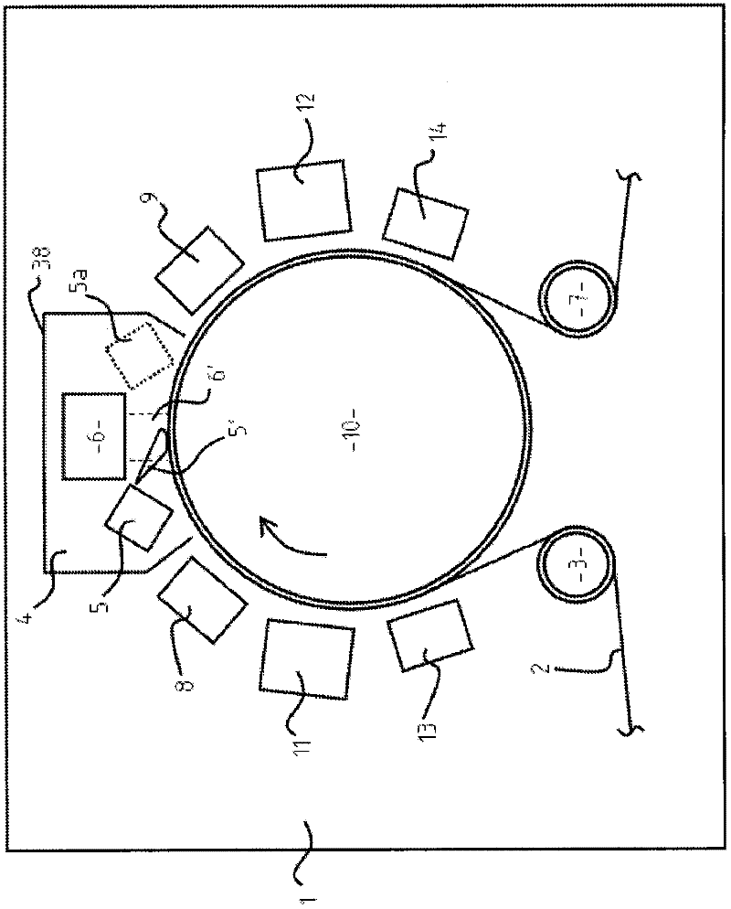
[0058] In this example, using two double-plate magnetrons, the plasma is Figure 6 way to transfer between them. Power is supplied by a DC magnetron power supply unit. The PID-controlled heated tube had an inner baffle, and the precursor TRPGDA was delivered to the heated tube on the opposite side of the moving sheet. A 30 mm slot machined in the tube towards the moving sheet provides the output precursor bundle. With over 200 watts of DC power on the two 2 inch diameter cathodes, these were placed 60 mm above the 150 mm coating drum carrying the moving sheet. In Argon 2x10 -20.2 ml precursor was transported in 1.5 min through a 20 mm slot positioned 50 mm away from the sheet at a pressure of mbar and at a 20 mm diameter heated transfer tube fitted in the 25 mm space between the cathodes Grooves, these precursors are aligned to intersect a large proportion of the electron flux at the substrate surface from the two cathodes. The substrate was coated at 30 meters per minute...
example 3
[0060] In this example, use Figure 5a and 5b installation. The plasma source was a 4 inch sputter cathode with a very weak magnetic field and a 6 inch (oversized) reaction plate. The precursor source consisted of a heated precursor delivery tube (3 / 4 inch diameter) with a 4 mm exit hole in front of the 6 inch cathode surface and was centrally mounted with the exit hole facing the sheet 20 mm below the cathode, the precursor The volume source is 30 mm from the sheet surface and uses a 3x10 -1 Oxygen / nitrogen atmosphere at mbar. The cathode was run at 150 watts and the tube was heated to 260°C as the liquid acrylate was transported 4 inches away from the 4 mm tube outlet and 180° opposite the exit hole. The acrylate was delivered through the metering needle valve and the resulting coating was a well cured acrylate deposit with excellent adhesion and good uniformity in the machine and cross directions.
PUM
| Property | Measurement | Unit |
|---|---|---|
| thickness | aaaaa | aaaaa |
Abstract
Description
Claims
Application Information