Method and device for machining insulating ceramic by reciprocating wire-cut electrical discharge machining
A technology of insulating ceramics and electric discharge wire, which is applied in the field of reciprocating electric discharge wire cutting processing of insulating ceramics, can solve the problems of poor processing surface quality and low processing accuracy, and achieve stable processing, reduce processing costs, and save costs Effect
- Summary
- Abstract
- Description
- Claims
- Application Information
AI Technical Summary
Problems solved by technology
Method used
Image
Examples
Embodiment 1
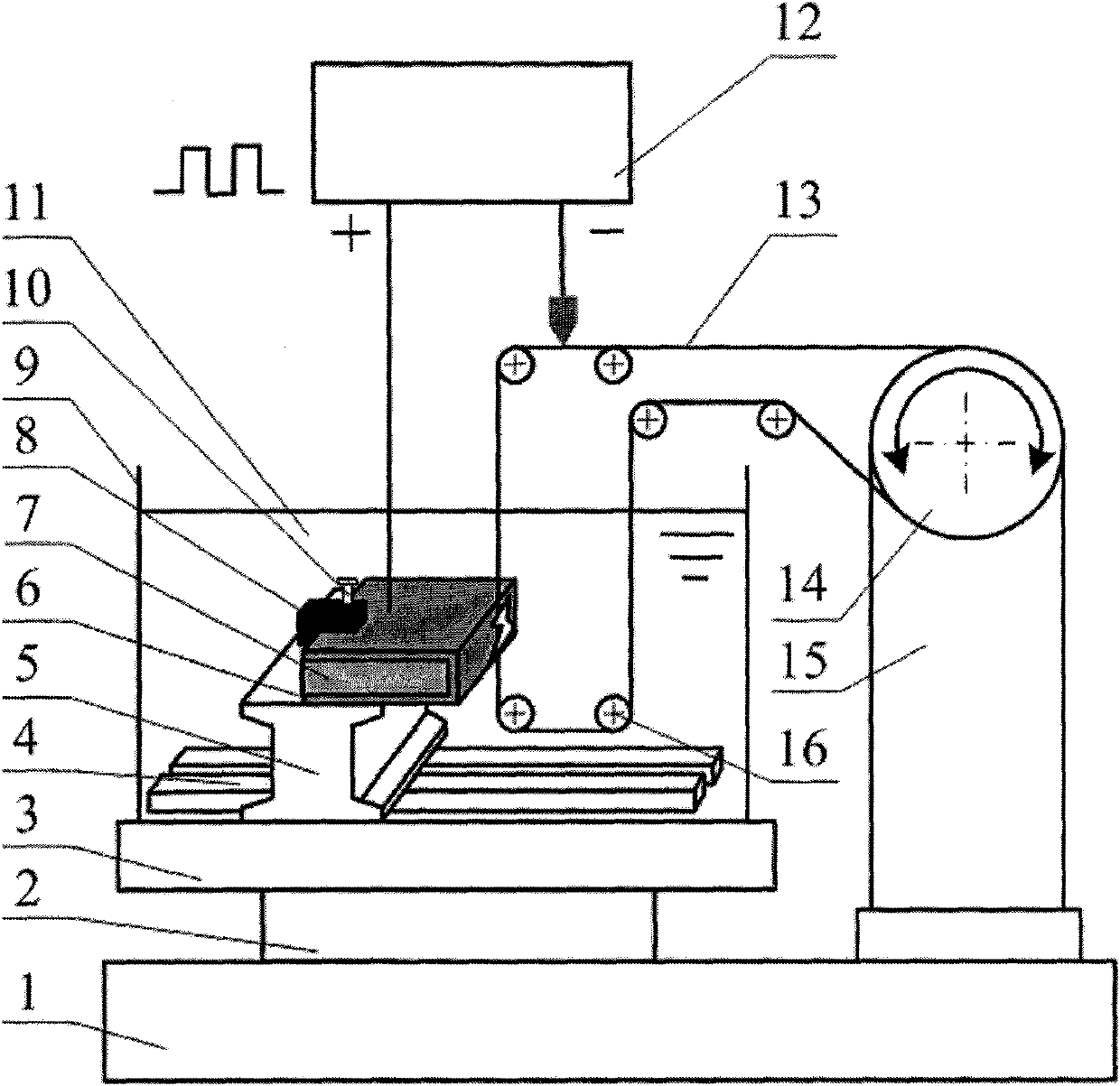
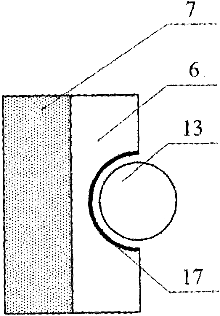
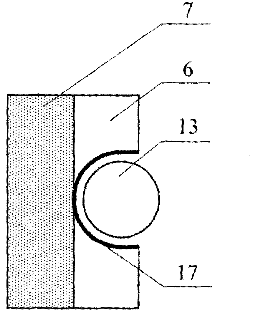
[0045] The schematic diagram of the reciprocating wire EDM processing method for insulating ceramics is as follows figure 1 As shown, the insulating ceramic 7 is pre-attached to the auxiliary electrode 6, and the electrode wire 13 is wound on the wire storage drum 14 of the wire feeding device 15 through the guide wheel 16 on the machine tool, and the wire storage drum motor ( figure 1 (not shown in ) drives the wire storage drum to do reciprocating rotary motion, installs the insulating ceramic 7 workpiece with the auxiliary electrode on the workpiece support 5 of the reciprocating wire electric discharge machine tool and immerses it in the kerosene working fluid 11, and puts the The positive and negative poles of the high-frequency pulse power supply 12 are respectively connected to the auxiliary electrode 6 and the electrode wire 13. The workbench of the machine tool drives the insulating ceramic 7 workpiece to move according to the predetermined trajectory, and spark discha...
Embodiment 2
[0048] Schematic diagram of the structure of the reciprocating wire electric discharge machining device for insulating ceramics, as shown in Figure 5 shown. The insulating ceramic reciprocating wire EDM processing device is mainly composed of: machine bed 1; wire feeding device 15; wire frame column 18; sixth guide wheel 19; wire storage barrel 14; first guide wheel 20; wire frame beam 21 ; Storage drum motor 22; L-shaped wire frame 23; No. 5 guide wheel 24; Conductive block 25; No. 2 guide wheel 26; No. 4 guide wheel 27; Electrode wire 13; Position adjusting screw rod 29; working liquid tank 9; sealing rubber pad 30; workbench 4; machine tool Y axis 3; machine tool X axis 2;
[0049] Wherein, the wire frame column 18 is fixed on the machine bed 1 by screws, one end of the wire frame beam 21 is fixed on the wire frame column 18 with a screw, and the L-shaped wire frame 23 is fixed with screws below the other end of the wire frame beam 21; Guide wheel 20 and No. 2 guide whee...
PUM
 Abstract
Description
Claims
Application Information
 - R&D
- Intellectual Property
- Life Sciences
- Materials
- Tech Scout
- Unparalleled Data Quality
- Higher Quality Content
- 60% Fewer Hallucinations
Browse by: Latest US Patents, China's latest patents, Technical Efficacy Thesaurus, Application Domain, Technology Topic, Popular Technical Reports.
© 2025 PatSnap. All rights reserved.Legal|Privacy policy|Modern Slavery Act Transparency Statement|Sitemap|About US| Contact US: help@patsnap.com


