Cold crucible vacuum inductive smelting device having energy beam auxiliary heat source

A vacuum induction melting and auxiliary heat source technology, applied in lighting and heating equipment, crucible furnaces, furnaces, etc., can solve problems such as inability to melt refractory metals and alloys, and achieve uniform structure, favorable compactness and consistency, and accurate composition Effect

Inactive Publication Date: 2011-09-14
张森
View PDF5 Cites 15 Cited by
  • Summary
  • Abstract
  • Description
  • Claims
  • Application Information

AI Technical Summary

Problems solved by technology

[0022] The technical problem to be solved by the present invention is to overcome the defect that the temperature of the existing vacuum cold crucible induction smelting equipment is difficult to reach above 2000°C, and it is impossible to smelt high-quality refractory metals and alloys, and to provide a method capable of preparing accurate, Cold crucible vacuum induction melting equipment with energy beam auxiliary heat source for uniform, consistent and dense refractory metals and alloys

Method used


Image

  • Cold crucible vacuum inductive smelting device having energy beam auxiliary heat source
  • Cold crucible vacuum inductive smelting device having energy beam auxiliary heat source
  • Cold crucible vacuum inductive smelting device having energy beam auxiliary heat source

Examples


preparation Embodiment 1

[0059] Preparation Example 1: Smelting of Metal Tungsten

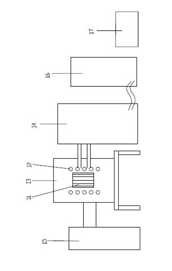
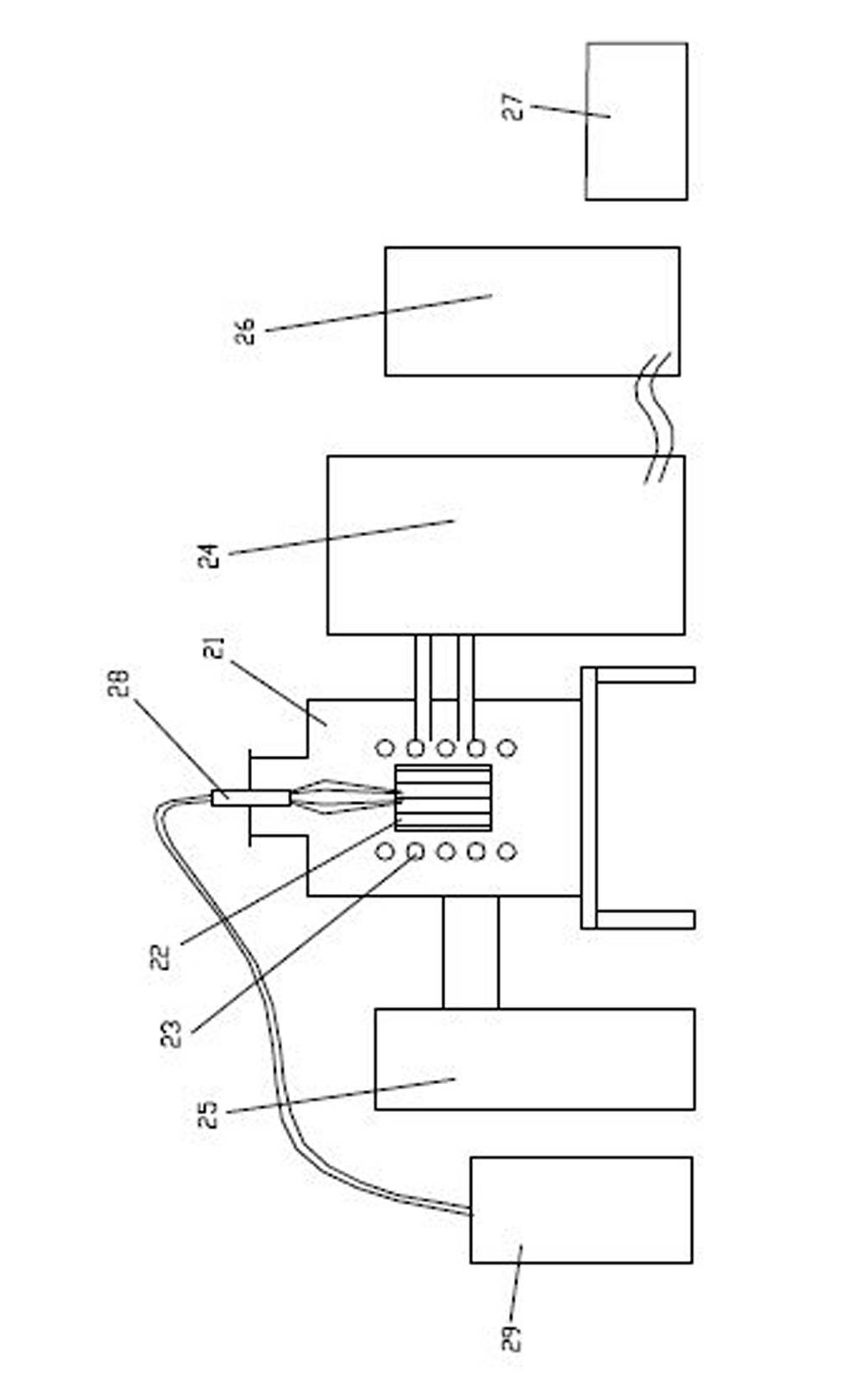
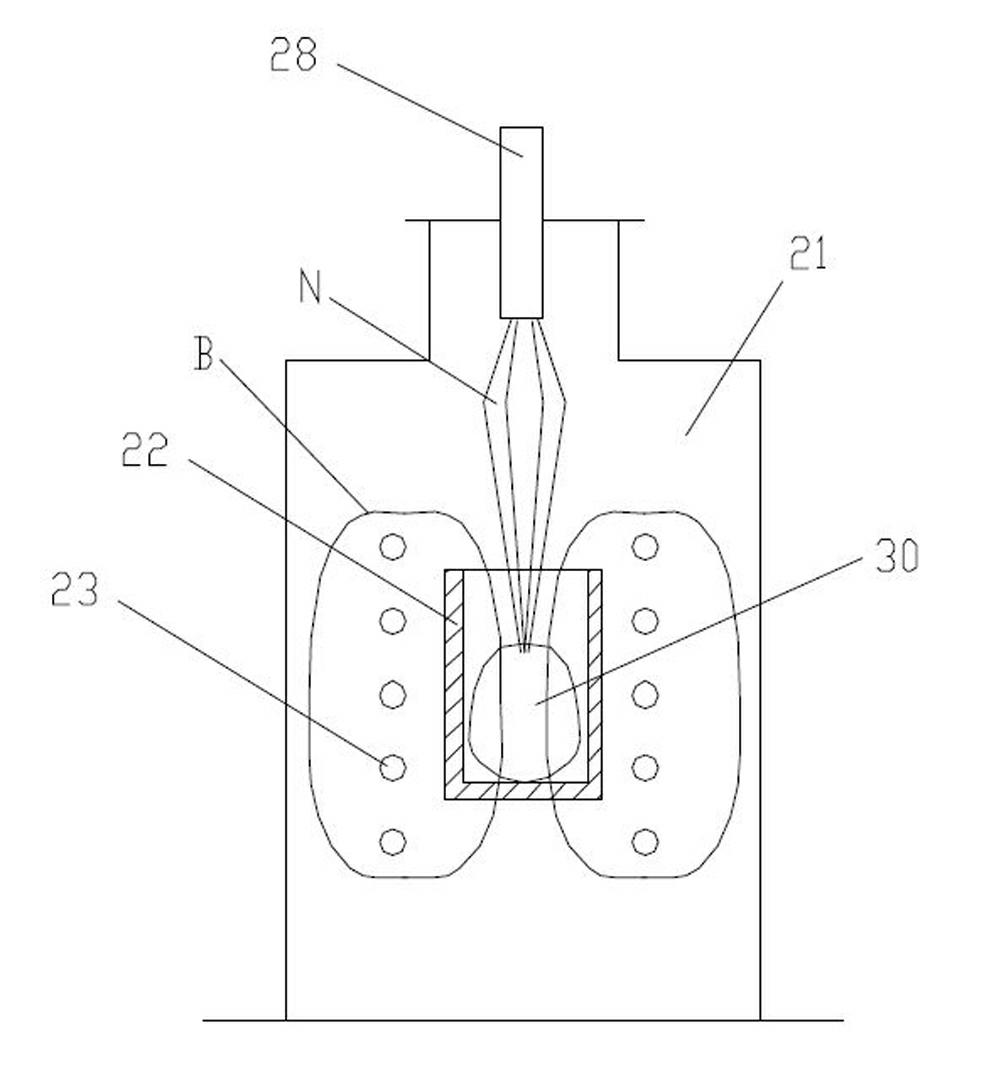
[0060] Put 10kg compacted tungsten powder billet into figure 2 In the cold crucible 22 of the shown cold crucible vacuum induction melting furnace, the power of the intermediate frequency power supply is 250kw, and the frequency is 15kHz. In this smelting furnace, the energy beam emitting head 28 and the energy beam generator 29 as the auxiliary heat source adopt an arc beam—the tungsten electrode is installed above the cold crucible 22, and the power of the DC power supply supplying the electrode is 100kw.

[0061] After the equipment is started, vacuumize first, and the vacuum degree reaches 5×10 -3 Pa is filled with 0.05MPa high-purity argon, and then the intermediate frequency power supply 24 is started to heat the charge to 1200°C. At this time, start the DC power supply to supply power to the electrode, and form a molten pool with a temperature exceeding 3600°C in the charge. Increase the power delivered by t...

preparation Embodiment 2

[0063] see Figure 4 , this embodiment adds a tilting pouring mechanism on the basis of the first embodiment. At the end of smelting, the energy beam emission is stopped, but the electromagnetic field continues to work, while the cold crucible 22 is tilted, and the melt 30 is poured into the casting mold 31 .

preparation Embodiment 3

[0065] see Figure 5 , this embodiment adds a bottom injection mechanism on the basis of the first embodiment. At the end of smelting, both the energy beam N and the electromagnetic field B continue to work, and at the same time, the injection port 32 at the bottom of the cold crucible 22 is opened, so that the melt 30 is injected into the casting mold 31 through the injection port 32 .


PUM


Abstract

The invention relates to a cold crucible vacuum inductive smelting device having an energy beam auxiliary heat source, which comprises a vacuum chamber, a cold crucible, an induction coil, a high frequency/intermediate frequency induction power supply used for supplying electric power to the induction coil, a vacuum argon-filling system, a control cabinet, a cooling system used for cooling the cold crucible, an energy beam launching head and an energy beam generator, wherein the cold crucible is arranged in the vacuum chamber; the induction coil is arranged in the vacuum chamber; the induction coil is encircled on the exterior of the cold crucible; the energy beam launching head is arranged on the top of the vacuum chamber and is positioned above the cold crucible; the energy beam generator is connected to the energy beam launching head; and the energy beam generator is used for generating an energy beam and transmitting the energy beam to the energy beam launching head. The device provided by the invention can be used for preparing the refractory metal and alloy which are characterized by accurate and uniform components, consistent tissues and compact materials.

Description

technical field [0001] The invention relates to equipment for melting refractory metals and their alloys, in particular to a cold crucible vacuum induction melting equipment with an energy beam auxiliary heat source for melting refractory metals and their alloys. Background technique [0002] Refractory metals (see the table below) generally refer to metals with a melting point of 1800-3400°C, such as tungsten, rhenium, tantalum, molybdenum, niobium, hafnium, vanadium, chromium, zirconium and other metals. Sometimes, titanium with a melting point of 1660°C is also fall into this category. [0003] Metal Tungsten W Rhenium Re Tantalum Ta Molybdenum Mo Niobium Nb Hafnium Hf Vanadium V Chromium Cr Zirconium Zr Titanium Ti Melting point (°C) 3410 3180 2996 2610 2468 2227 1890 1857 1852 1660 [0004] The above metals and alloys based on them (ie, refractory metals and their alloys) have ...

Claims


Application Information

Patent Timeline
Patent Type & Authority Applications(China)
IPC IPC(8): F27B14/06F27B14/14
Inventor 李碚张森
Owner 张森
Why Eureka
Try Eureka