Surface covering cutting tool

A technology of cutting tools and surface coating, which is applied in the field of surface coating cutting tools, can solve the problems of short life, damage of cBN coating tools, and inability to exert sufficient cutting performance, etc., and achieve the effect of prolonging life

Active Publication Date: 2011-09-28
MITSUBISHI MATERIALS CORP
View PDF9 Cites 5 Cited by
  • Summary
  • Abstract
  • Description
  • Claims
  • Application Information

AI Technical Summary

Problems solved by technology

[0010] In recent years, the FA of cutting processing equipment has been very remarkable. On the other hand, there is a strong demand for cutting labor and energy saving and cost reduction in cutting processing. With this, cutting processing has become more advanced in addition to general cutting conditions. The tendency to perform cutting under severe conditions, especially in the above-mentioned conventional cBN-coated tools that form a hard film by physical vapor deposition, does not cause special problems when used in cutting under general conditions, but using this When a high load acts on the blade during high-speed intermittent cutting, cracks will occur at the brazed portion of the cBN sintered material and the cemented carbide base material, and the progress of the crack will cause the cBN-coated tool to be damaged. Therefore, the service life is relatively short, and the long-term Cannot exhibit sufficient cutting performance during use
[0011] In addition, there is a problem that although the improvement shown in Patent Document 3 is attempted for the brazed portion of the cBN sintered material and the cemented carbide base material, although the occurrence of cracks during brazing can be prevented, cracks during cutting cannot be suppressed. The generation of cracks, the progression of cracks, and the extension of tool life are still not possible

Method used


Image

  • Surface covering cutting tool
  • Surface covering cutting tool
  • Surface covering cutting tool

Examples


Embodiment

[0053] cBN powder, TiN powder, AlN powder, Ni powder, Al powder, Co powder, and W powder each having an average particle diameter in the range of 0.5 to 4 μm were prepared as raw material powders, and these raw material powders were blended into the blends shown in Table 1. Composition, and after wet mixing with a ball mill for 80 hours and drying, press with a pressure of 120MPa to form a green compact with a size of diameter: 50mm×thickness: 1.5mm, and then in a vacuum atmosphere with a pressure of 1Pa, in the range of 900 to 1300°C After sintering the compact under the condition of maintaining the predetermined temperature for 60 minutes, it is used as a spare sintered body for blades, and the spare sintered body is prepared separately with a composition of Co: 8% by mass, WC: remaining, and a diameter of 50 mm. × Thickness: WC-based cemented carbide support sheets of 2mm size are stacked, loaded into a conventional ultra-high pressure sintering device, and under normal cond...


PUM


Abstract

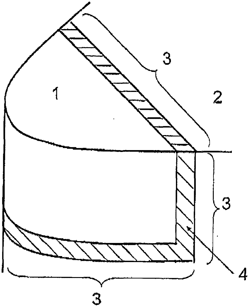
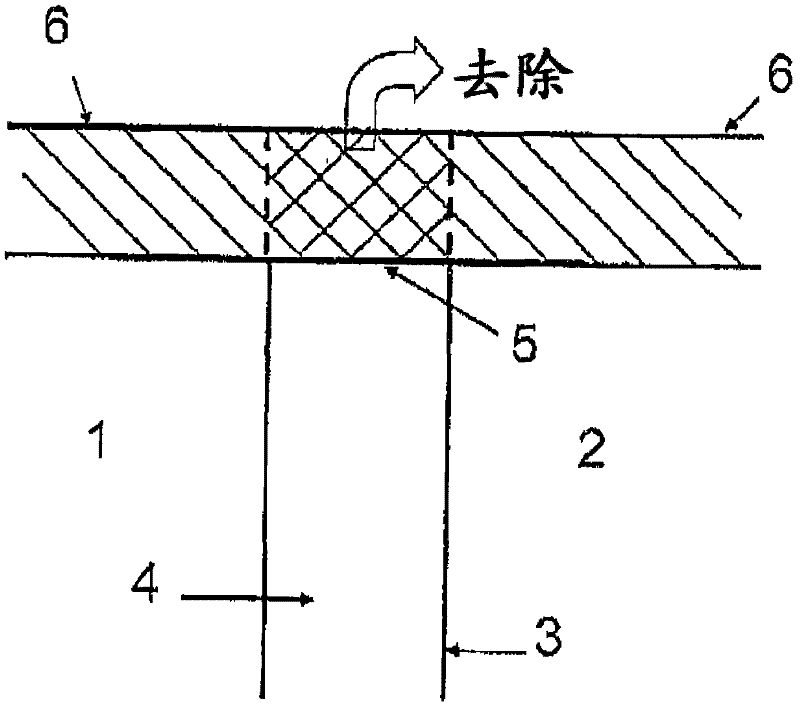
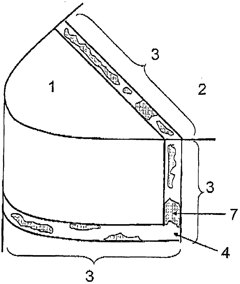
The invention provides a surface covering cutting tool, which is capable of preventing breakage of brazing part during brazing and joining a tool base and a hard alloy base material. The brazing material of the brazing part is used to join the tool base formed by cubic crystal boron nitride base superhigh pressure sintered materials and a hard alloy base material, furthermore, the surface covering cutting tool is also characterized in that, during forming a hard film on the surfaces of the tool base and the hard alloy base material via physical vapor deposition, the whole surface of the brazing material exposed at the surface of the brazing part is set to be A, and the whole surface of the brazing material exposed at the surface in a contact with the hard film is set to be B, via setting of B / A to be 0.05<= B / A<=0.8, stress generated between the hard film and the brazing part is reduced, and generation of crack and progress of crack are prevented.

Description

technical field [0001] The present invention relates to a kind of use brazing to join the cubic boron nitride (hereinafter referred to as cBN) based ultra-high pressure sintered material (hereinafter referred to as cBN sintered material) constituting the blade to the cemented carbide base material, and, through physical vapor deposition A surface-coated cutting tool in which a hard coating layer is formed on the surface of a cBN sintered material and a cemented carbide base material (hereinafter referred to as a cBN-coated tool). Background technique [0002] Conventionally, it is known that cBN sintered material is used as a tool material with low affinity with the workpiece in the cutting of iron-based workpieces such as steel and cast iron, and it is also widely known that the improvement of wear resistance, A cBN-coated tool that forms a hard coating layer on the tool surface by physical vapor deposition from the viewpoint of improving tool life. [0003] For example, a...

Claims


Application Information

Patent Timeline
IPC IPC(8): B23B27/14B23K35/24B23K1/00B23P15/28
Inventor 西山满康高冈秀充冈田义一佐伯卓司
Owner MITSUBISHI MATERIALS CORP
Why Eureka
Try Eureka