Method and device for exploiting natural gas hydrate in permafrost region

A mining method and technology of natural gas, which is applied in the fields of mining fluid, earthwork drilling, wellbore/well components, etc. It can solve the problems of increased pump power consumption and equipment investment, lowered NGH reservoir temperature, and unavailable mining, etc., and is easy to automate Effects of operation and remote control, promotion of NGH decomposition, and low mining cost

Active Publication Date: 2011-10-12
GUANGZHOU INST OF ENERGY CONVERSION - CHINESE ACAD OF SCI
View PDF11 Cites 46 Cited by
  • Summary
  • Abstract
  • Description
  • Claims
  • Application Information

AI Technical Summary

Problems solved by technology

The various NGH mining technologies mentioned above have their own advantages and disadvantages and application fields. At present, there is no internationally recognized large-scale NGH mining method that is technically, economically, safe, and environmentally feasible.
[0004] The pressure and temperature of NGH reservoirs in permafrost regions are relatively low, and the amount of free water is small, which is suitable for pumping and depressurization. The decomposition rate of "self-protection effect" is extremely slow. Once the temperature drops below 0°C, it will also cause "ice blockage" and "secondary hydrate" formation, resulting in a significant decrease in the permeability of NGH reservoirs; in addition, if mining is located on the permafrost floor For the above-mentioned NGH, the depressurization method converts all NGH into ice, making the mining impossible; therefore, the depressurization method alone is difficult to be effective in the commer

Method used


Image

  • Method and device for exploiting natural gas hydrate in permafrost region
  • Method and device for exploiting natural gas hydrate in permafrost region

Examples


Embodiment Construction

[0015] The scheme of the present invention is described in detail below with preferred embodiments thereof.

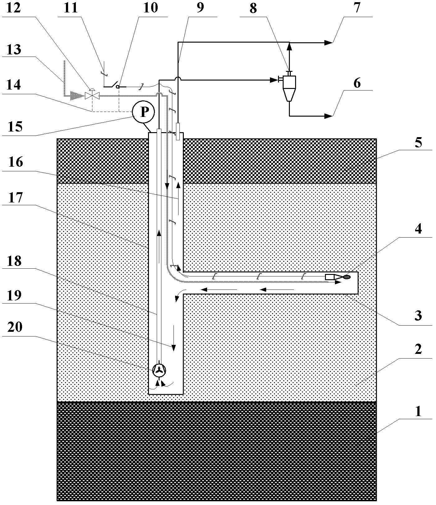
[0016] The natural gas hydrate mining method in the permafrost area of ​​the present invention comprises the steps of:

[0017] Inject oxygen-containing gas into the horizontal well to ignite NGH or NGH decomposition gas in the horizontal well for combustion;

[0018] Use deep well pumps to pump the liquid water produced by the decomposition of NGH in vertical wells and horizontal wells to the ground;

[0019] Collect decomposed water and decomposed gas.

[0020] In a specific embodiment, the implementation of the above-mentioned natural gas hydrate exploitation method in the permafrost region of the present invention may be:

[0021] (1) Drilling vertical wells and horizontal wells, which can be drilling vertical wells and horizontal wells in hydrate reservoirs in permafrost regions by using existing drilling technology;

[0022] (2) Install pumping and depressuriz...


PUM


Abstract

The invention discloses a method and a device for exploiting natural gas hydrate in a permafrost region. The device comprises a water-pumping depressurization system, an underground in-situ combustion heating system, a gas collection system and a control system. The water pumping depressurization system comprises a water delivery pipe, a deep-well pump and a gas-liquid separator, wherein the deep-well pump is arranged at the bottom of a vertical well; and the gas-liquid separator is connected with the deep-well pump by the water delivery pipe. The underground in-situ combustion heating system comprises an electronic ignition device and an oxygen-containing gas conveying pipe, wherein the electronic ignition device is connected with a ground power supply by a power switch; and the oxygen-containing gas conveying pipe is connected with an external gas supply system and paved from the ground to the electronic ignition device through the vertical well. The gas collection system comprises a gas collection pipe which is arranged at a well head of the vertical well. The control system comprises a pressure sensor, the power switch and a regulation valve, wherein the regulation valve is arranged on the oxygen-containing gas conveying pipe; and the control system controls the aperture of the regulation valve and the on and off of the power switch according to a pressure, which is measured by the pressure sensor, of the vertical well. By the invention, the synchronous continuous exploitation of depressurization and underground in-situ combustion heating can be realized.

Description

technical field [0001] The invention belongs to the field of energy technology, and relates to natural gas hydrate exploitation technology, in particular to a natural gas hydrate exploitation method and device in permafrost regions. Background technique [0002] Natural Gas Hydrate (NGH for short) is a non-stoichiometric, ice-like, cage-type crystalline compound formed by low-molecular-weight hydrocarbons in water and natural gas under low temperature and high pressure conditions. NGH has the characteristics of a host-guest material. Water molecules (hosts) form a spatial lattice structure through hydrogen bonding, and gas molecules (guests) fill the cavities between the water molecule lattices through van der Waals forces with water molecules. There are extensive natural gas hydrate formation conditions under the seabed and terrestrial permafrost. It is estimated that the organic carbon stored in the form of natural gas hydrate on the earth accounts for 53% of the global to...

Claims


Application Information

Patent Timeline
IPC IPC(8): E21B43/243E21B43/34E21B43/30
CPCE21B41/0099
Inventor 陈朝阳李小森黄宁生张郁颜克凤曾志勇吕秋楠李刚
Owner GUANGZHOU INST OF ENERGY CONVERSION - CHINESE ACAD OF SCI
Why Eureka
Try Eureka