Dephosphorization method of semi-steel

A dephosphorization and slagging technology, applied in the field of steelmaking, can solve the problems of low dephosphorization rate of converter, insufficient heat source, slow slagging speed and other problems, achieve high dephosphorization efficiency, reduce steelmaking production cost, and good dephosphorization effect Effect

Inactive Publication Date: 2011-10-19
PANZHIHUA IRON AND STEEL +2
View PDF4 Cites 42 Cited by
  • Summary
  • Abstract
  • Description
  • Claims
  • Application Information

AI Technical Summary

Problems solved by technology

[0006] One of the purposes of the present invention is to overcome the problem of insufficient heat so...

Method used


Image

  • Dephosphorization method of semi-steel
  • Dephosphorization method of semi-steel
  • Dephosphorization method of semi-steel

Examples


Embodiment 1

[0028] The parameters of the six-hole oxygen lance nozzle of a steel plant are shown in Table 1:

[0029] Table 1 Parameters of six-hole oxygen lance nozzle

[0030] Nozzle type

Number of holes (a)

Throat diameter (mm)

Angle of nozzle hole (degree)

Mach number

Combination

6 holes around

Φ33

16

2.05

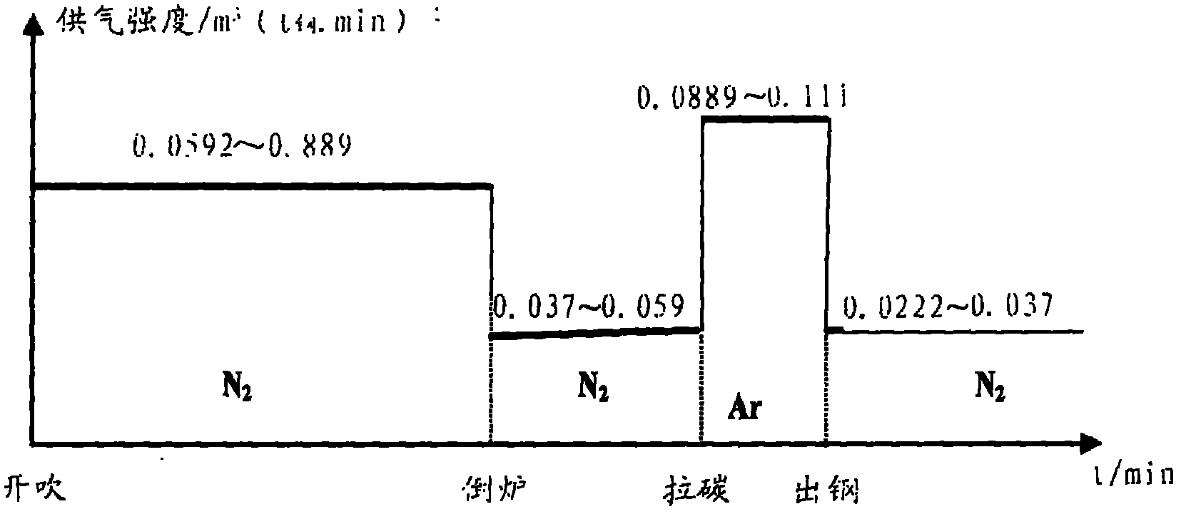
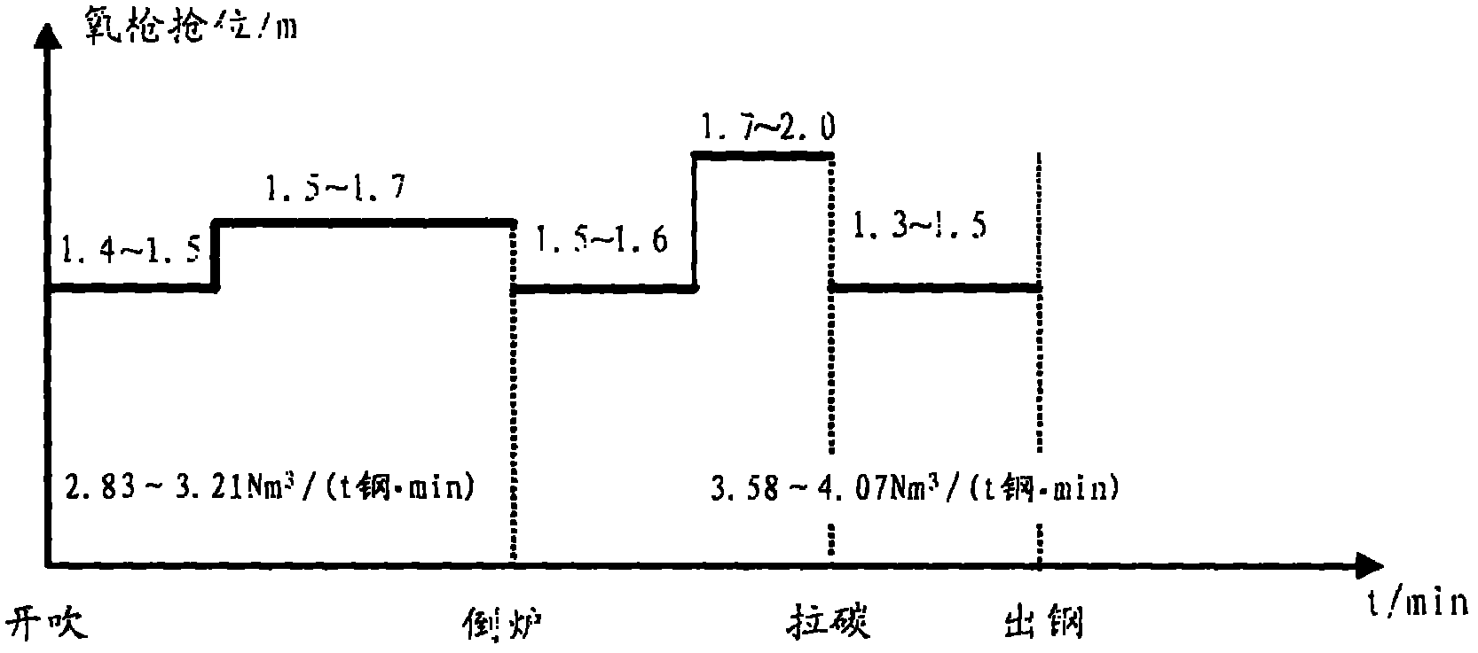
[0031] An oxygen lance with parameters as described in Table 1 was used for smelting on a 120-ton converter in a steel plant. The oxygen flow rate during the initial dephosphorization is 23000Nm 3 / h, working pressure is 0.70MPa, oxygen supply intensity is 2.84m 3 / (t steel·min), the bottom blowing nitrogen flow rate is 100Nm when blowing 3 / h, bottom blowing air supply intensity is 0.0592m 3 / (t steel·min). At this time, the low gun position is mainly used to promote slag removal, and the gun position is 1.4m. The amount of the first batch of slagging materials is: active lime 13kg / t semi-steel; slagging material high-magnesium lime is added 11kg / t semi-steel; slagging...

Embodiment 2

[0036] The parameters of the six-hole oxygen lance nozzle of a steel plant are shown in Table 3:

[0037] Table 3 Parameters of six-hole oxygen lance nozzle

[0038] Nozzle type

Number of holes (a)

Throat diameter (mm)

Angle of nozzle hole (degree)

Mach number

Combination

6 holes around

Φ32

18

2.08

[0039] A 120-ton converter in a steel plant uses oxygen lances with parameters as described in Table 3 for smelting. The oxygen flow rate during the initial dephosphorization is 25000Nm 3 / h, working pressure is 0.75MPa, oxygen supply intensity is 3.21m 3 / (t steel·min), the bottom blowing nitrogen flow rate is 120Nm when blowing 3 / h, the gas supply intensity is 0.0889m 3 / (t steel·min). The amount of the first batch of slagging material added is: active lime 22kg / t semi-steel; slagging material high-magnesium lime added 20kg / t semi-steel; slagging material composite slagging agent added 22kg / t semi-steel. Add slag conditioning agent in the late stage of the first deph...


PUM


Abstract

The invention provides a dephosphorization method of semi-steel. The method comprises the following steps: adopting a six-hole oxygen gun to perform sectional smelting through a way of adjusting the oxygen supply strength of the oxygen gun, namely first dephosphorization smelting, adding a first batch of slag-making materials, controlling the oxygen supply strength of a top-blowing oxygen gun at 2.83-3.21Nm3/(t steel. min), simultaneously bottom-blowing nitrogen, smelting and deslagging; performing second dephosphorization smelting, adding a second batch of the slag-making materials, controlling the oxygen supply strength of the top-blowing oxygen gun at 3.58-4.07Nm3/(t steel. min), bottom-blowing the nitrogen during the time period from the beginning of the second dephosphorization smelting to carbon catching, bottom-blowing argon during the time period from the carbon catching to the terminal point of converting, smelting, stopping slag, tapping for getting molten steel with the content of a phosphorus element, which is not more than 0.008% by weight percentage, and performing the operation of remaining the slag after the tapping. By adopting the method, the dephosphorization effect is good, the dephosphorization efficiency is high, the smooth operation of the smelting process of a converter can be ensured, the steel-making production cost can be reduced and the semi-steel can be adopted for producing low-phosphorus steel with high grade and high added value.

Description

Technical field [0001] The invention relates to the technical field of steelmaking, and more specifically, to a method for dephosphorizing semi-steel. Background technique [0002] Since the mass percentage of carbon in the semi-steel is 3.4% to 4.0%, and the content of silicon and manganese heating slag-forming elements are all traces, the semi-steel smelting has fewer acidic slag-forming substances, single slag components, and heat in the converting process. Insufficiency and other characteristics, this makes semi-steel steelmaking more difficult compared to molten iron slag, and the dephosphorization effect is not significant. After the pretreatment of vanadium-containing molten iron, the mass percentage of sulfur in the semi-steel can be controlled within 0.015%, but the phosphorus content in the vanadium-containing molten iron does not have any pretreatment measures; the mass percentage of phosphorus in the semi-steel is 0.055%~ 0.090%, the final phosphorus fluctuation of c...

Claims


Application Information

Patent Timeline
IPC IPC(8): C21C7/064
Inventor 陈均梁新腾杨森祥曾建华陈永刘荣蒂陈天明李清春李平凡曾耀先
Owner PANZHIHUA IRON AND STEEL
Why Eureka
Try Eureka