A dual frequency narrowband bandpass filter

A filter and resonator technology, applied in waveguide-type devices, electrical components, circuits, etc., can solve the problems of increased cost, large system space, occupation, etc., and achieve the effect of reducing insertion loss and improving harmonic suppression characteristics.

Inactive Publication Date: 2014-10-01
SHANGHAI UNIV
View PDF3 Cites 0 Cited by
  • Summary
  • Abstract
  • Description
  • Claims
  • Application Information

AI Technical Summary

Problems solved by technology

[0003] Traditional filters can no longer meet the needs of wireless communication systems, and now that spectrum resources are scarce, people's demand for large-capacity transmission of information is becoming more and more urgent, so dual-frequency or multi-frequency filters can well meet wireless communication requirements. Communication System Requirements
The traditional design is to add multiple filters in the communication system, which not only increases the cost, but also takes up more system space

Method used


Image

  • A dual frequency narrowband bandpass filter
  • A dual frequency narrowband bandpass filter
  • A dual frequency narrowband bandpass filter

Examples


Embodiment 1

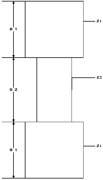
[0032] Embodiment one: see Figure 6 , the dual-band narrowband bandpass filter includes a three-layer structure: a metal microstrip line on the front, a dielectric plate layer in the middle and an input and output port, and a metal coating on the reverse side of the dielectric plate. The metal microstrip line structure is: A first resonator composed of a section of low impedance line and a step impedance line connected to it, and a second resonator composed of a quarter-wavelength uniform impedance line and a feeder connected to a rectangular short microstrip line; due to the first resonance The structure of the transformer is symmetrical, so it can be analyzed by the theory of odd and even modes; the input and output ports of the feeder are on the same horizontal line.

Embodiment 2

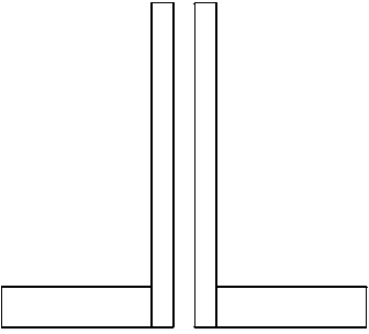
[0033] Embodiment 2: This embodiment is basically the same as Embodiment 1, and the special feature is: the step impedance line is formed by connecting a short impedance line (11) at the end of two parallel coupling lines (7), realizing a new coupling. The rectangular short microstrip line (9) is located at the corner where the quarter-wavelength uniform impedance line (8) connects to the feeder line (12), thereby achieving excellent harmonic suppression characteristics. The dielectric plate layer (5) is a dielectric constant =10.2 of the dielectric board, the thickness of the dielectric board h =0.635mm.

Embodiment 3

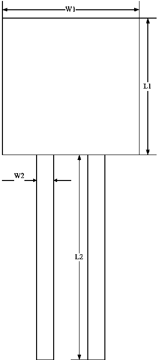
[0034] Embodiment three: this embodiment is basically the same as embodiment two, and the special features are: Figure 6 It is a structural schematic diagram of the present embodiment. Through design, simulation and optimization, the specific dimensions of the microstrip ultra-narrowband bandpass filter are finally determined as follows:

[0035] L1=7.3mm, L2=10.0mm, L3=8.4mm, L4=0.8mm

[0036] W1=6.0mm, W2=0.6mm, W3=0.6mm, W4=1.1mm

[0037] G=0.2mm, D=0.2mm,

[0038] Based on the above method, a microstrip filter with a center frequency of 2.62GHz / 5.98GHz and a relative bandwidth of about 6% is designed, and is simulated and debugged by the electromagnetic simulation software Sonnet.

[0039] Figure 7 The frequency response simulation results of a dual-band filter implemented with a conventional structure are shown.

[0040] Figure 8 The simulated structure of the microstrip filter is shown, and the simulated results show that the present invention has great advantage...


PUM


Abstract

The invention relates to a novel double-frequency narrow-band bandpass filter. The novel double-frequency narrow-band bandpass filter comprises a metal microstrip line on the front surface, a medium plate layer, an input port and an output port on the middle part, and a metal plating layer on the rear side of a medium plate, wherein in the metal microstrip line, a resonator consisting of a section of low impedance line and a stepped impedance line connected with the low impedance line, and a novel resonator formed by connecting a quarter wavelength uniform impedance line and a feeder with a rectangular short microstrip line. The resonator structure is symmetrical, so that an odd-even mode theory can be used for analyzing the resonator structure; and the input port and the output port of the feeder are in the same level line. A transmission zero is inserted into a stop band between two pass bands, a zero position in a transmission characteristic curve can be flexibly adjusted, the stop band characteristics are improved, and a transmission zero is inserted outside two center frequencies respectively to improve out-of-band rejection characteristics. The novel double-frequency narrow-band bandpass filter has a simple structure and extremely high frequency selectivity and meets the requirements on miniaturization.

Description

technical field [0001] The invention relates to a dual-frequency narrow-band band-pass filter, which belongs to the category of dual-frequency band-pass filters with transmission zero points in the technical field of wireless communication. Background technique [0002] With the rapid development of communication technology, especially the development of wireless communication technology, the requirements for filters in wireless communication systems are getting higher and higher. In 1997, the Institute of Electrical and Electronics Engineers (IEEE) formulated the 802.11 Wireless Local Area Network (WLAN) protocol, which opened a new milestone for the development of wireless communication. [0003] Traditional filters can no longer meet the needs of wireless communication systems, and now that spectrum resources are scarce, people's demand for large-capacity transmission of information is becoming more and more urgent, so dual-frequency or multi-frequency filters can well me...

Claims


Application Information

Patent Timeline
Patent Type & Authority Patents(China)
IPC IPC(8): H01P1/212
Inventor 李国辉胡金萍顾卿灵马德臣钱斐斐
Owner SHANGHAI UNIV
Why Eureka
Try Eureka