Simultaneous flue gas desulfurization and denitrification system and method based on hydrogen peroxide

A hydrogen peroxide, desulfurization and denitrification technology, applied in chemical instruments and methods, separation methods, dispersed particle separation, etc., can solve problems such as catalyst blockage, wear, and catalyst poisoning, and achieve low energy consumption, low investment costs, and convenient use Effect

Inactive Publication Date: 2011-12-14
ZHONG POLERIS GREENTECH HLDG
View PDF0 Cites 17 Cited by
  • Summary
  • Abstract
  • Description
  • Claims
  • Application Information

AI Technical Summary

Problems solved by technology

[0003] There are two main types of nitrogen oxide removal methods: one is to control the production of nitrogen oxides through the combustion process, and the efficiency is about 30-50%. This method has low efficiency and is easy to cause slagging in the furnace pipeline
The second type of flue gas denitrification technology is the selective catalytic red...

Method used


Image

  • Simultaneous flue gas desulfurization and denitrification system and method based on hydrogen peroxide
  • Simultaneous flue gas desulfurization and denitrification system and method based on hydrogen peroxide
  • Simultaneous flue gas desulfurization and denitrification system and method based on hydrogen peroxide

Examples


Embodiment 1

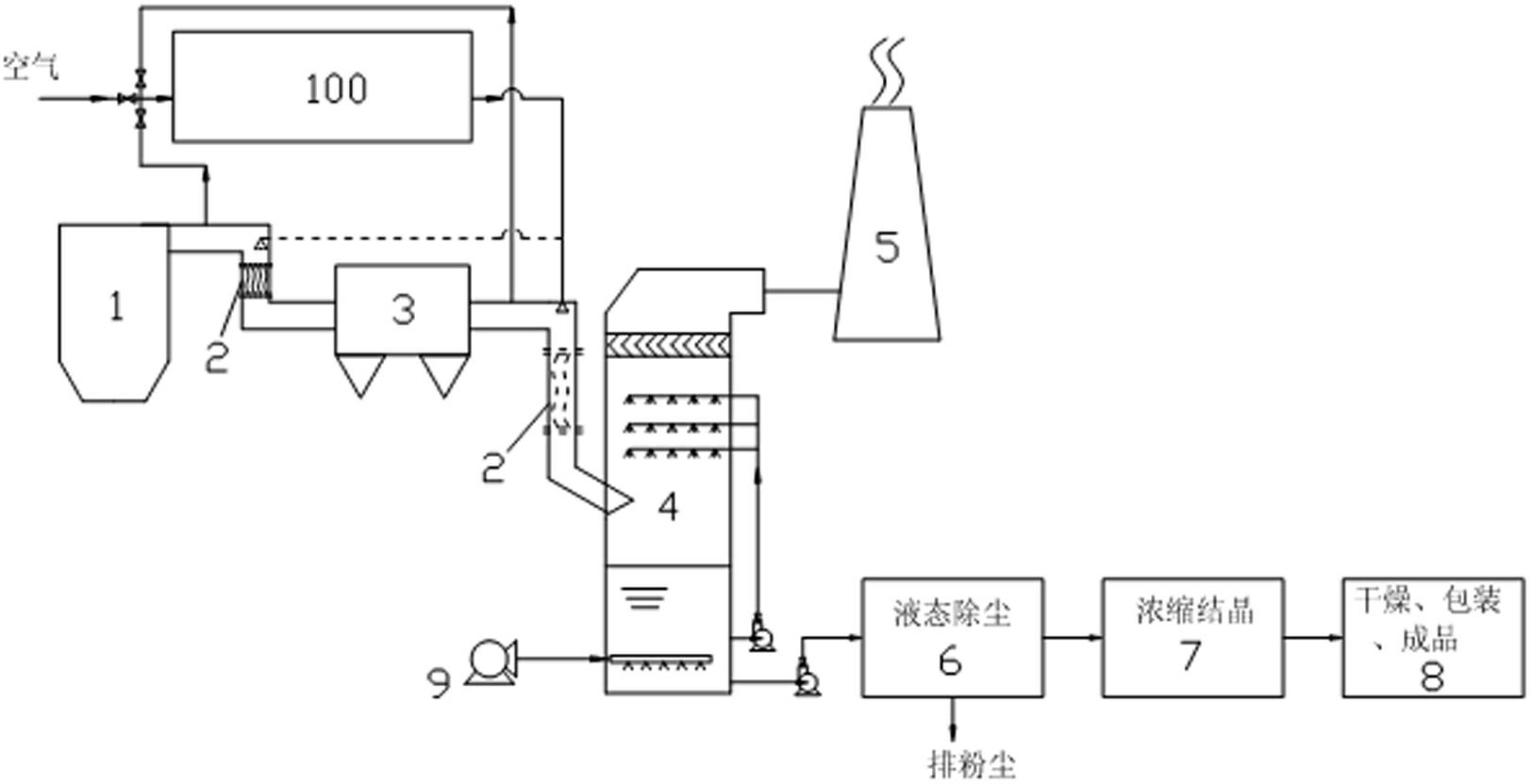
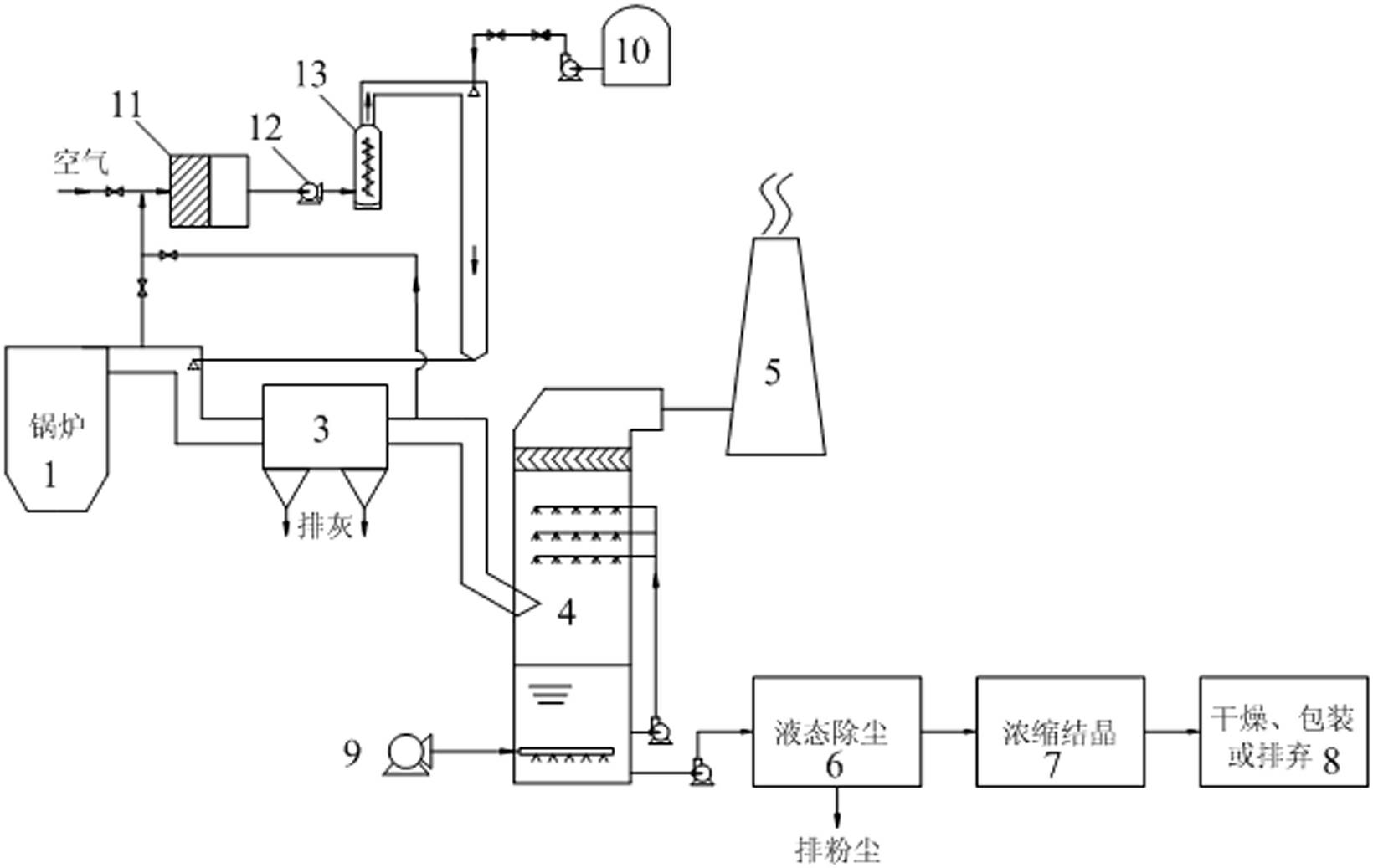
[0028] like figure 2 As shown, in this embodiment, the flue gas generating device 1 is a boiler, and the hydrogen peroxide vaporization system includes a filter device 11, a fan 12, a heating device 13 and a hydrogen peroxide storage tank 10; the filter device 11 One end of each is connected with the first pipeline, the second pipeline and the third pipeline, and the other end is connected with the fan 12; the other end of the fan 12 is connected with the heating device 13, and the other end of the heating device 13 is connected with the fifth pipeline , the fifth pipeline is connected to one end of the fourth pipeline, and the other end of the fourth pipeline is connected to a gas distribution device; the fifth pipeline is provided with an atomizing nozzle, and the atomizing nozzle is connected to a fourth A control valve, the fourth control valve is connected with a one-way valve, the one-way valve is connected with a supply pump, and the supply pump is connected with a hyd...

Embodiment 2

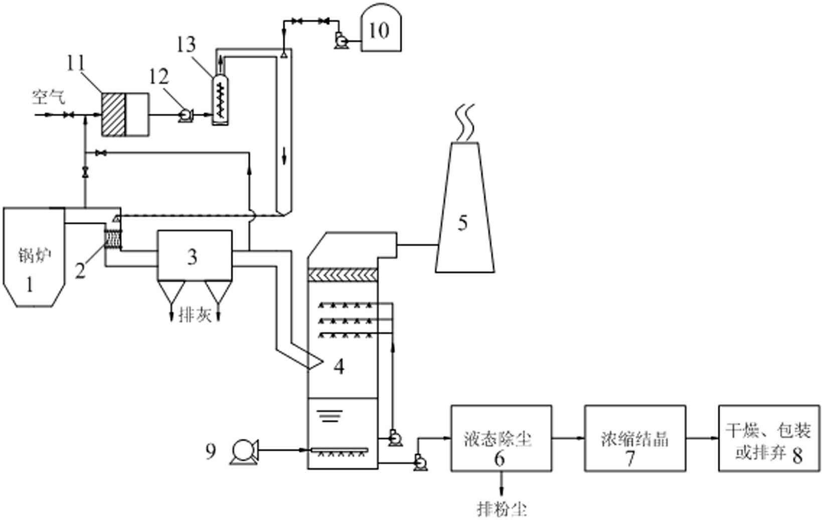
[0032] like image 3 As shown, the difference from Example 1 is that a reaction chamber 2 is provided on the flue between the gas distribution device and the dust collector 3, such as Figure 4 and 5 As shown, the reaction chamber includes a first hollow cylinder 14 and a second hollow cylinder 15 sleeved in the first hollow cylinder 14, and the length of the second hollow cylinder 15 is shorter than that of the first hollow cylinder Body length 14, one end of the first hollow cylinder 14 and one end of the second hollow cylinder 15 are respectively connected to the two ends of a hollow circular platform side wall 16, the other end of the first hollow cylinder 14 and the second hollow cylinder The other ends of the two hollow cylinders 15 are respectively connected to the two ends of the side wall of another hollow circular platform 17 .

[0033] When using the system of Example 2 to carry out desulfurization and denitrification operations, wherein the moles of hydrogen pero...

Embodiment 3

[0036] like Figure 6 As shown, the difference from Example 1 is that the gas distribution device is arranged on the flue between the dust collector 3 and the absorption tower 4 .

[0037] When using the system of Example 3 for desulfurization and denitrification operations, wherein the moles of hydrogen peroxide gas injection are 1.8 times the moles of nitric oxide, and the oxidation time is 0.5 seconds, in the present embodiment, the first control valve and The third control valve is closed, and the second control valve is opened, so that the flue gas in the flue between the dust collector and the absorption tower enters the heating device, and the temperature of the flue gas in the flue between the dust collector and the absorption tower is 110°C. The temperature of the gas coming out of the heating device is 250°C. The detection instrument used for nitrogen oxides and sulfur dioxide in the flue gas is: NOVA2000, and the NOx in the flue gas generated by the flue gas generat...


PUM

PropertyMeasurementUnit
Denitrification efficiencyaaaaaaaaaa

Abstract

The invention relates to a system and method for simultaneous desulfurization and denitrification of flue gas based on the action of hydrogen peroxide. The system includes a flue gas generating device, a dust collector connected to the flue gas generating device through a flue, an absorption tower connected to the dust collector through the flue, the top of the absorption tower is connected to a chimney, and the bottom of the absorption tower is connected to an oxidation fan and Liquid dedusting device, the liquid dedusting device is connected with a salt solution concentration and crystallization device, the salt solution concentration and crystallization device is connected with a finished product packaging device, and the flue is connected with a hydrogen peroxide vaporization system, which is used to provide peroxide hydrogen gas. The simultaneous flue gas desulfurization and denitrification system based on hydrogen peroxide in the present invention can make the flue gas achieve a denitrification rate of more than 85% and a desulfurization rate of more than 95%. The system has low investment cost, low energy consumption and convenient use. It is an SCR It is incomparable with the denitrification method of the ozone oxidation method.

Description

technical field [0001] The invention relates to a system and method for simultaneous desulfurization and denitrification of flue gas based on the action of hydrogen peroxide. Background technique [0002] Nitrogen oxides and sulfur oxides produced during the utilization of coal, natural gas, and heavy oil, as well as some chemical production, have caused serious harm to the atmospheric environment. At present, there are several types of desulfurization technologies generally adopted for air pollution control, such as dry method, semi-dry method and wet method. Dry and semi-dry methods have the disadvantage of low desulfurization efficiency. Limestone / gypsum method, ammonia method, magnesium oxide method, double subtraction method and other wet methods are widely used at present, but these technologies are powerless in terms of denitrification. [0003] There are two main types of nitrogen oxide removal methods: one is to control the production of nitrogen oxides through th...

Claims


Application Information

Patent Timeline
IPC IPC(8): B01D53/76B01D53/78B01D53/86B01D53/96B01D53/60
Inventor 王宜民翁颖佟飞
Owner ZHONG POLERIS GREENTECH HLDG
Why Eureka
Try Eureka