Supercharge Your Innovation With Domain-Expert AI Agents!

Catalyst regeneration unit for methanol to olefins

A technology of methanol to olefins, regeneration device, applied in catalyst regeneration/reactivation, molecular sieve catalyst, physical/chemical process catalyst, etc., can solve the problem that only one can be provided.

Active Publication Date: 2011-12-14
CHINA PETROLEUM & CHEM CORP +1
View PDF7 Cites 14 Cited by
  • Summary
  • Abstract
  • Description
  • Claims
  • Application Information

AI Technical Summary

Problems solved by technology

In this method, the regenerator is a bubbling bed, and only one stage of regeneration is set up, which has the disadvantage of only providing a regenerated catalyst with a carbon deposition amount.
[0006] As is well known in the art, to efficiently utilize the C4 and above hydrocarbons produced in the methanol-to-olefins process, one of the schemes is to use the methanol-to-olefins catalyst to further convert them into low-carbon olefins, but due to the similarities and differences in the reaction characteristics, the methanol conversion The amount of carbon deposition required is different from the amount of carbon deposition required for the conversion of hydrocarbons above C4. The existing technology only sets one stage of regeneration, and there is a problem that only one regenerated catalyst with a carbon deposition amount can be provided.

Method used


Image

  • Catalyst regeneration unit for methanol to olefins
  • Catalyst regeneration unit for methanol to olefins

Examples


Embodiment 1

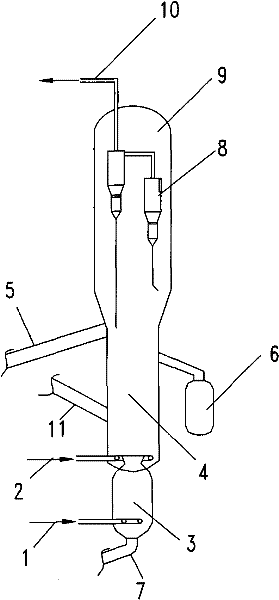
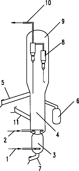
[0019] in such as figure 1 In the small regeneration device shown, the regeneration temperature is controlled by an external full-return mixing heat extractor. The gas-solid cyclone separator adopts two stages. The regeneration temperature in the first regeneration zone is 630°C, and the regeneration temperature in the second regeneration zone is 670°C. Compressed air is used as the regeneration medium, and SAPO-34 molecular sieve catalyst is used. The bed density of the first regeneration zone is 385 kg / m3, and the bed density of the second regeneration zone is 427 kg / m3. The bottom of the regeneration zone is connected. The catalyst in the first regeneration zone enters the second regeneration zone through the pipeline at the bottom. The first regeneration inclined pipe, the second regeneration inclined pipe and the inclined pipe to be raw are all equipped with catalyst sampling equipment. The catalyst samples taken out are Infrared carbon and sulfur analyzer measures the am...

Embodiment 2

[0021] in such as figure 1 In the small-scale regeneration device shown, the regeneration temperature is controlled by an external full-return mixing heat extractor. The gas-solid cyclone separator adopts three stages. The regeneration temperature in the first regeneration zone is 650°C, and the regeneration temperature in the second regeneration zone is 685°C. Compressed air is used as the regeneration medium, and SAPO-34 molecular sieve catalyst is used. The bed density of the first regeneration zone is 402 kg / m3, and the bed density of the second regeneration zone is 439 kg / m3. The bottom of the regeneration zone is connected. The catalyst in the first regeneration zone enters the second regeneration zone through the pipeline at the bottom. The first regeneration inclined pipe, the second regeneration inclined pipe and the inclined pipe to be raw are all equipped with catalyst sampling equipment. The catalyst samples taken out are Infrared carbon and sulfur analyzer measure...

Embodiment 3

[0023] in such as figure 1In the small-scale regeneration device shown, the regeneration temperature is controlled by an external full-return mixing heat extractor. The gas-solid cyclone separator adopts the first stage, and the regeneration temperature in the first regeneration zone is 618°C, and the regeneration temperature in the second regeneration zone is 650°C. Compressed air is used as the regeneration medium, and SAPO-34 molecular sieve catalyst is used. The bed density of the first regeneration zone is 395 kg / m3, and the bed density of the second regeneration zone is 454 kg / m3. The bottom of the regeneration zone is connected. The catalyst in the first regeneration zone enters the second regeneration zone through the pipeline at the bottom. The first regeneration inclined pipe, the second regeneration inclined pipe and the inclined pipe to be raw are all equipped with catalyst sampling equipment. The catalyst samples taken out are Infrared carbon and sulfur analyzer m...


PUM


Abstract

The invention relates to a device for generating catalyst for use in preparation of olefins from methanol. The catalyst reactivation device mainly solves the problem that a regenerator in the technology of preparing olefins from methanol only can provide a regenerated catalyst with the carbon deposition quantity. The device for generating catalyst for use in preparation of olefins from methanol mainly comprises a first regenerated area 4, a second regenerated area 3, an inclined tube to be regenerated 11, a first regenerated inclined tube 5, a second regenerated inclined tube 7, heating equipment 6, gas-solid separation equipment 8 and a settlement area 9, wherein the upper part of the first regenerated area 4 is connected with the settlement area 9, and the lower part of the first regenerated area 4 is connected with the second regenerated area 3; the gas-solid separation equipment 8 is positioned in the settlement area 9; the inclined tube to be regenerated 11 is connected with the lower part of the first regenerated area 4; the first regenerated inclined tube 5 is connected with the first regenerated area 4; the second regenerated inclined tube 7 is connected with the second regenerated area 3; regenerated medium air inlet pipelines are arranged at bottoms of the first regenerated area 4 and the second regenerated area 3; and a flue gas outlet pipeline 10 is arranged on thetop of the settlement area 9. By the technical scheme, the problem is better solved. The catalyst reactivation device can be used for the industrial production of low-carbon olefins.

Description

technical field [0001] The invention relates to a catalyst regeneration device for methanol to olefin. technical background [0002] Low-carbon olefins, namely ethylene and propylene, are two important basic chemical raw materials, and their demand is increasing. Generally, ethylene and propylene are produced through petroleum routes, but due to the limited supply and high price of petroleum resources, the cost of producing ethylene and propylene from petroleum resources continues to increase. In recent years, people have begun to vigorously develop the technology of converting alternative raw materials into ethylene and propylene. Among them, an important class of alternative raw materials for the production of light olefins are oxygenates, such as alcohols (methanol, ethanol), ethers (dimethyl ether, methyl ethyl ether), esters (dimethyl carbonate, methyl formate Esters), etc., these oxygenated compounds can be converted from coal, natural gas, biomass and other energy s...

Claims


Application Information

Patent Timeline
IPC IPC(8): B01J38/20B01J29/90C07C1/20C07C4/06C07C11/04C07C11/06
CPCY02P20/52Y02P20/584Y02P30/20Y02P30/40
Inventor 齐国祯张惠明王华文
Owner CHINA PETROLEUM & CHEM CORP
Features
  • R&D
  • Intellectual Property
  • Life Sciences
  • Materials
  • Tech Scout
  • Unparalleled Data Quality
  • Higher Quality Content
  • 60% Fewer Hallucinations
Learn More