
A multifunctional communication switch box

A transition box and multi-functional technology, applied in the direction of instrumentation, electrical digital data processing, etc., can solve the problems of poor versatility and compatibility, bottlenecks in production efficiency, impact on service life, etc., and achieve the reduction of programming and testing time, The effect of saving manufacturing cost and improving production efficiency

Inactive Publication Date: 2011-12-14
HUIZHOU DESAY SV AUTOMOTIVE
View PDF6 Cites 14 Cited by
  • Summary
  • Abstract
  • Description
  • Claims
  • Application Information

AI Technical Summary

Problems solved by technology

Whether it is a dedicated programmer or a dedicated communication adapter, it can only achieve a single protocol communication, and only one product can be connected externally.
There are two disadvantages of this mode: first, the versatility and compatibility are not strong, and the communicator needs to be replaced if there is a slight change in the programming or test object. Writer and communication adapter. When producing B-type products, it must be replaced with a B-type burner and communication adapter. This frequent replacement not only requires repeated insertion and removal of the burner and adapter, but also replaces The corresponding tooling racks also need to switch on and off the production computer, which not only affects the service life of tooling, racks, and equipment, but also seriously affects production efficiency.
The second is that a programmer or communication adapter can only operate one product at a time, and it is impossible to connect multiple products at a time, which brings a bottleneck to the improvement of production efficiency.

Method used


Image

  • A multifunctional communication switch box
  • A multifunctional communication switch box
  • A multifunctional communication switch box

Examples


Embodiment Construction

[0016] In order to facilitate the understanding of those skilled in the art, the present invention will be further described in detail below with reference to the drawings and embodiments.

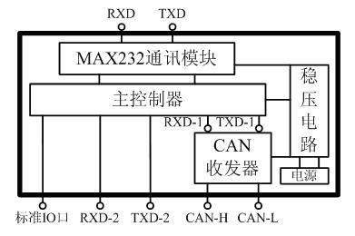
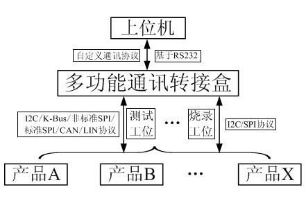
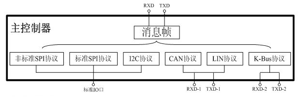
[0017] Such as figure 1 As shown, the multi-functional adapter box disclosed by the present invention is composed of five parts: a main control unit, a MAX232 communication module, a CAN transceiver, a voltage stabilizing circuit and a power supply. The power supply and the voltage stabilizing circuit are used for the power supply of the other three parts. The CAN transceiver is used to realize the communication of the physical layer of the CAN and LIN protocols. The CAN transceiver uses a CAN transceiver chip, which is connected to the communication transfer box through two pins of CAN-H and CAN-L. The MAX232 communication module is used to realize the serial communication between the upper computer and the main control unit based on a custom protocol. The upper computer needs to be conn...


PUM


Abstract

The invention relates to a multifunctional communication transfer box, which includes a main control unit, an uplink communication unit and a downlink communication interface unit connected to the main control unit. The uplink communication unit is used to realize the communication based on the serial port between the main control unit and the upper computer, and the downlink communication interface unit is used to realize the communication between the main control unit and the product to be operated based on I2C, K-Bus, non-standard SPI, standard SPI, CAN And the communication of LIN interface. The control of the entire communication process and the conversion of the communication protocol are realized by the self-defined communication protocol placed in the main control unit. The communication adapter box of the present invention can realize the operation of testing or burning multiple products at the same time through the connection with the upper computer, which eliminates various inconveniences caused by the incompatibility of special communication boxes and greatly improves the production efficiency. efficiency, saving manufacturing costs.

Description

technical field [0001] The invention relates to the field of electronic equipment for production and testing, in particular to a multifunctional communication transfer box. Background technique [0002] In the manufacturing process of automotive electronic products, the burning and automatic testing of the product EEPROM are generally involved. The communication protocols involved in EEPROM programming include I2C or SPI, and the communication protocols involved in automated testing include I2C, K-Bus, non-standard SPI, standard SPI, CAN and LIN. In the existing production mode, the product EEPROM is programmed using a dedicated programmer, and the automated test uses a dedicated communication adapter. Whether it is a dedicated programmer or a dedicated communication adapter, it can only achieve a single protocol communication, and can only be connected to one external product. There are two disadvantages of this mode: first, the versatility and compatibility are not stron...

Claims


Application Information

Patent Timeline
Patent Type & Authority Applications(China)
IPC IPC(8): G06F13/38
Inventor 林振国梁元
Owner HUIZHOU DESAY SV AUTOMOTIVE
Learn More