Adaptive current source drive circuit

A technology of driving circuits and current sources, applied in electrical components, output power conversion devices, etc., can solve the problems of speeding up the switching speed of power MOSFETs, increasing switching time and switching loss, increasing switching time and loss, etc., to achieve efficiency optimization, The effect of reducing high-frequency drive loss and switching loss, and reducing drive loss

Inactive Publication Date: 2011-12-14
NANJING UNIV OF AERONAUTICS & ASTRONAUTICS
View PDF3 Cites 15 Cited by
  • Summary
  • Abstract
  • Description
  • Claims
  • Application Information

AI Technical Summary

Problems solved by technology

[0003]Figure 1(a) and (b) show the traditional voltage source driver (Voltage Source Drivers) mode, which has two shortcomings: 1) Since the drive circuit is charged and discharged in RC mode, it can effectively drive The current will decrease with the change of the gate drive voltage, which increases the switching time and switching loss. The parasitic inductance (line inductance, package inductance) in the driving circuit will further reduce the effective driving current and increase the switching time and loss.

Method used


Image

  • Adaptive current source drive circuit
  • Adaptive current source drive circuit
  • Adaptive current source drive circuit

Examples


Embodiment Construction

[0043] The technical solutions of the present invention will be described in detail below in conjunction with the accompanying drawings.

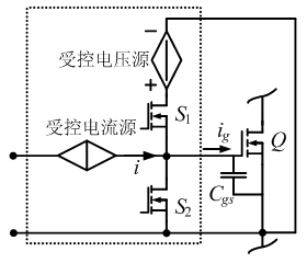
[0044] image 3 A conceptual diagram of the adaptive CSD drive is given. The controlled sources in the figure are the driving voltage and the driving current, and the controlled quantities can be the voltage, current and frequency in the power circuit. The driving voltage and driving current can be adaptively adjusted according to the actual state of the circuit.

[0045] The self-adaptive current source driving circuit provided by the present invention can be divided into CS inductive current continuous type and discontinuous type according to the inductive current situation of the current source (Current Source, CS).

[0046] one. Continuous current drive circuit

[0047] Figure 4 Given the continuous half-bridge CSD circuit, its main working waveform diagram is as follows Figure 5 shown.

[0048] exist[ t 1 , t 2 ] period, t...


PUM


Abstract

Disclosed is an adaptive current source drive circuit, comprising a current source drive circuit and a voltage adjusting circuit, wherein the voltage adjusting circuit feeds back the parameter change by acquiring a main circuit, obtains a reference voltage, and dynamically adjusts the driving circuit of the current source drive circuit, thus realizing adaptive current source driving. According to the circuit structure, the high frequency driving loss and the switch loss is reduced, and the system efficiency is optimized within the wide load scope.

Description

technical field [0001] The invention belongs to the technical field of power device drive circuits. Background technique [0002] With the rapid development of power electronics technology, the power supply is developing towards high power density and high efficiency. The operating frequency of traditional low-power converters is generally hundreds of kilohertz. The passive components of the converter (such as capacitors and inductors) are relatively large, the dynamic response is slow, and the volume and weight are large, which directly reduces the power density of the converter. Therefore, high-frequency converters and high power density are the development trend of low-power converters. As a bridge between the signal circuit and the main power circuit, the rationality and correct design of the drive circuit have an important impact on the entire converter system. [0003] Figure 1(a) , (b) Given the traditional voltage source driver (Voltage Source Drivers) method, the...

Claims


Application Information

Patent Timeline
IPC IPC(8): H02M1/08
Inventor 张之梁胥鹏程蔡卫
Owner NANJING UNIV OF AERONAUTICS & ASTRONAUTICS
Why Eureka
Try Eureka