
Anti-biological clogging device for drip-irrigation system

An anti-biological and ozone generator technology, applied in watering devices, botanical equipment and methods, climate change adaptation, etc., can solve the problem that the anti-biological clogging effect and durability cannot be guaranteed, affect the efficiency and quality of drip irrigation, Limit the popularization and application of drip irrigation technology and other issues, and achieve the effect of improving convection and diffusion capacity, simple structure, and less mechanical failure

Inactive Publication Date: 2012-10-03
FARMLAND IRRIGATION RES INST CHINESE ACAD OF AGRI SCI
View PDF1 Cites 0 Cited by
  • Summary
  • Abstract
  • Description
  • Claims
  • Application Information

AI Technical Summary

Problems solved by technology

However, the sterilizing function of the technical solutions of the above two patents is only limited to the emitter. The biological matter that grows and reproduces in the water delivery pipeline before the emitter of the drip irrigation system and behind the head hub filter can still cause blockage of the emitter. Anti-bioclogging effect and durability are still not guaranteed
In addition, photocatalyst substances, as the name suggests, need to be stimulated by light to produce bactericidal activity, which is obviously not suitable for underground drip irrigation systems
The biological clogging of the drip irrigation system has seriously affected the irrigation efficiency and quality of the drip irrigation, which has limited the popularization and application of the drip irrigation technology, especially the underground drip irrigation technology. There is an urgent need for better anti-biological clogging methods and devices for the drip irrigation system.

Method used


Image

  • Anti-biological clogging device for drip-irrigation system

Examples


Embodiment Construction

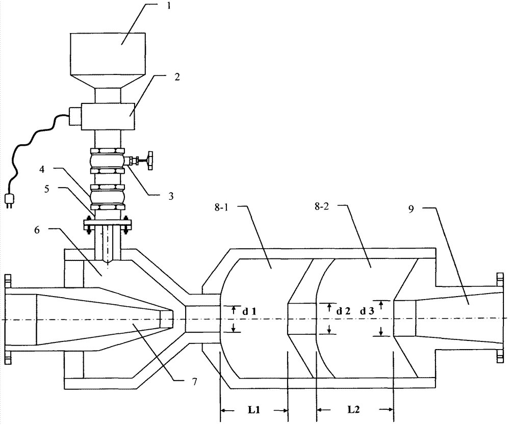
[0023]An anti-biological clogging device for a drip irrigation system, as shown in the accompanying drawings, including: an air filter 1, an ozone generator 2, an air intake gate valve 3, a check valve 4, an air intake pipe 5, an air injection chamber 6, and a jet nozzle 7 , a primary oscillation chamber 8-1, a secondary oscillation chamber 8-2, a gradual change channel 9, the outlet end of the air filter 1 passes through the ozone generator 2, the intake gate valve 3, the check valve 4, the intake pipe 5 and The air inlet end of the upper part of the gas injection chamber 6 is connected, and the end with a large flow section of the jet nozzle 7 is connected to the filter outlet end located at the head of the drip irrigation system. Inside the chamber 6, the horizontal outflow end of the gas injection chamber 6 is connected to the horizontal inflow end of the first-stage oscillation chamber 8-1 through a circular throat with a diameter of d1, and the injection port of the jet n...


PUM


Abstract

The invention relates to an anti-biological clogging device for a drip-irrigation system. The drip-irrigation system is started, an air intake brake valve is opened, an ozone generator is started, and compressed water which comes from the head part of the drip-irrigation system is sprayed at high speed from a jet orifice of a jet nozzle so as to form the negative pressure in a gas injection cavity; and under the action of the negative pressure, the ozone generator ensures that ozone generated through air ionization enters the gas injection cavity through the air intake brake valve, a check valve and an air inlet pipe along with the air filtered by an air filter, and enters an oscillating cavity for vortex oscillation, stirring and aerification along with the high-speed water flow sprayed by the jet nozzle so as to form 'ozone water' of which gas and liquid are distributed uniformly, and the 'ozone water' enters the drip-irrigation system to kill microorganisms in flow channels and cansynchronously inhibit crop root systems from growing toward the direction of a water outlet of a drip irrigation emitter in an underground drip-irrigation system, so that the aim of biological clogging resistance of the drip-irrigation system is fulfilled. Compared with a method of injecting a chemical agent into irrigation water, the invention has the advantages that: the residue of harmful substances which can pollute the environment is not produced, and the risk of using dangerous chemical agents is avoided.

Description

Technical field: [0001] The invention belongs to the technical field of agricultural water-saving irrigation, and in particular relates to an anti-biological clogging device for a drip irrigation system. Background technique: [0002] Drip irrigation is a kind of local irrigation, which consists of five parts: the first hub, the main pipe, the branch pipe, the capillary pipe, and the sprinkler. ①The head hub is responsible for water intake, pressurization and water treatment, and is composed of water pumps, fertilizer tanks, filters, pressure gauges, flow meters and other components; ②The main pipe plays the role of water delivery; Crop water demand, distribute irrigation water to the irrigation area; ④ Capillary pipes are connected with branch pipes to send water to the roots of crops; ⑤ Irrigators, including: drippers, water outlets, etc., have different types and shapes to Moisten the soil at the root of the crop. Arranging drip irrigation capillaries and emitters under...

Claims


Application Information

Patent Timeline
Patent Type & Authority Patents(China)
IPC IPC(8): A01G25/02C02F1/78C02F1/50
CPCY02A40/22
Inventor 高胜国高任翔
Owner FARMLAND IRRIGATION RES INST CHINESE ACAD OF AGRI SCI
Learn More