Cu/Cu2O film material for reducing CO2 into organic fuel under catalysis

A thin film material, CO2 technology, used in organic chemistry, chemical/physical processes, physical/chemical process catalysts, etc.

Inactive Publication Date: 2011-12-21
余颖
View PDF2 Cites 27 Cited by
  • Summary
  • Abstract
  • Description
  • Claims
  • Application Information

AI Technical Summary

Problems solved by technology

[0004] But so far, there is no Cu electrode surface with Cu 2 Catalytic reduction of CO in the presence of O film 2 The report of the influence, the present invention fills up the blank in this aspect, and finds that Cu/Cu

Method used


Image

  • Cu/Cu2O film material for reducing CO2 into organic fuel under catalysis
  • Cu/Cu2O film material for reducing CO2 into organic fuel under catalysis
  • Cu/Cu2O film material for reducing CO2 into organic fuel under catalysis

Examples


Embodiment 1

[0030] p-type Cu 2 Preparation of O

[0031] p-type Cu 2 The preparation of O was carried out in a self-made electrolytic cell, which consisted of an anode chamber and a cathode chamber separated by an anion exchange membrane. The anode material is copper sheet, and the cathode material is titanium mesh. Add the mixed solution of the NaCl of 150g / L and the CTAB (hexadecyltrimethylammonium bromide) of 1g / L in the anode chamber before preparation, add the NaOH aqueous solution of 1mol / L in the cathode chamber, heat described The temperature of the solution is raised to 75°C, and the electrolysis starts. The reaction time is 10 minutes, and the current density during the reaction is controlled at 10A / m 2 , the anolyte was stirred continuously during the reaction. After the reaction was complete, the copper sheet was taken out and washed with distilled water. After drying, put it into an ethanol solution with a mass fraction of 0.1% BTA (benzotriazole) and soak for two hours,...

Embodiment 2

[0033] n-type Cu 2 O film preparation

[0034] Typical n-type Cu 2 O thin films were prepared by a simple boiling method. 0.01mol / L of CuSO 4 The solution was heated to a boiling state, and the copper piece was put into the boiling solution for 2 hours. After the reaction, the copper sheet was taken out, rinsed repeatedly with distilled water, and then dried to obtain n-type Cu / Cu 2 O film material.

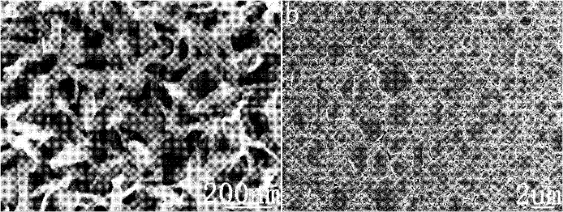
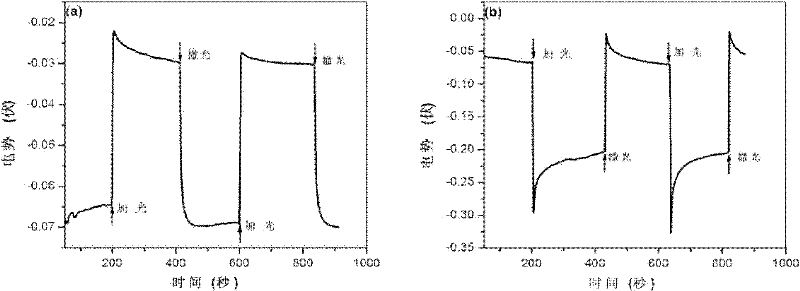
[0035] Cu / Cu prepared by embodiment 1 and 2 2 The electron micrographs and conductive properties of O thin film materials are shown in figure 2 and image 3 shown. Depend on figure 2 It can be seen that Cu with uniform size was obtained by both preparation methods 2 O, where p-type Cu 2 The O film is composed of nanoribbons, while the n-type Cu 2 The O film is formed by the accumulation of larger-sized micron-sized stone-like particles. Two kinds of Cu 2 O films are grown directly from the substrate, so the two Cu 2 The O films are all combined very tightly with ...


PUM


Abstract

The invention relates to a Cu/Cu2O film electrode for the photoelectrocatalytic reduction of CO2, which comprises p-type and n-type Cu2O films prepared on a Cu substrate by an electrochemical method and a chemical boiling method. Two Cu/Cu2O electrodes are used for the photocatalytic reduction, electrocatalytic reduction and photoelectrocatalytic reduction of the CO2 respectively; the two electrodes have catalytic activity on the CO2 reduction in three systems, and the selectivity of the electrodes on a product C2H4 is enhanced due to the existence of Cu2O; the two electrodes have the highestCO2 reduction efficiency in a photoelectrocatalytic system; p-type Cu2O and n-type Cu2O have low CO2 photocatalytic reduction efficiency in a photocatalytic system; the CO2 is reduced into the C2H4 through the electrocatalysis of the p-type Cu2O and the n-type Cu2O and the CO2 reduction efficiency of the p-type Cu2O is higher than that of the n-type Cu2O in an electrocatalytic system; and the yield of the C2H4 on the p-type Cu2O electrode and the yield of the C2H4 on the n-type Cu2O electrode are almost the same in the photoelectrocatalytic system and are 1.5 and 2.7 times that of the C2H4 inthe electrocatalytic system, and the CO2 reduction efficiency of the n-type Cu2O in the photoelectrocatalytic system is increased by more times. The composite electrode can be used for reducing the CO2 into the organic fuel under photoelectrocatalysis.

Description

technical field [0001] The present invention relates to catalytic reduction of CO 2 Cu / Cu mainly methane and ethylene 2 O thin film electrode material, Cu / Cu 2 O thin film electrode material is to deposit Cu on the surface of Cu 2 O film material. It belongs to the application field of converting greenhouse gas carbon dioxide into organic fuel. Background technique [0002] carbon dioxide (CO 2 ) is the highest stage oxidation product of carbon, similar to inert gas, in an extremely stable state, so looking for a CO 2 The effective way of transformation is the focus of social attention recently. Since Halmann discovered in 1978 that P-GaP electrodes can photoelectrically co-catalyze the reduction of CO 2 (Nature.1978:115), CO 2 Research on catalytic reduction has attracted more and more attention. [0003] Studies have shown that in the electrocatalytic reduction of CO 2 In the process, the electrode material used plays a crucial role, which determines the type and...

Claims


Application Information

Patent Timeline
IPC IPC(8): B01J23/72C07C9/04C07C11/04C07C1/12
CPCY02P20/52
Inventor 余颖闫丽丽邱明强
Owner 余颖
Why Eureka
Try Eureka