A flue gas purification system

A flue gas purification system and flue gas technology are applied in air quality improvement, chemical instruments and methods, dispersed particle separation, etc., and can solve the problems of large demand for ammonia water, large amount of fly ash, visual pollution of white smoke, etc. Simple, remove water vapor visual pollution, low cost effect

Active Publication Date: 2011-12-28
光大环保能源(苏州)有限公司 +1
View PDF6 Cites 16 Cited by
  • Summary
  • Abstract
  • Description
  • Claims
  • Application Information

AI Technical Summary

Problems solved by technology

[0009] The purpose of the present invention is to provide a flue gas purification system to solve the problems of large amount of fly ash, undecomposed dioxin, large demand for ammonia water and visual pollution of white smoke in the existing flue gas purification system

Method used


Image

  • A flue gas purification system
  • A flue gas purification system

Examples


Embodiment 1

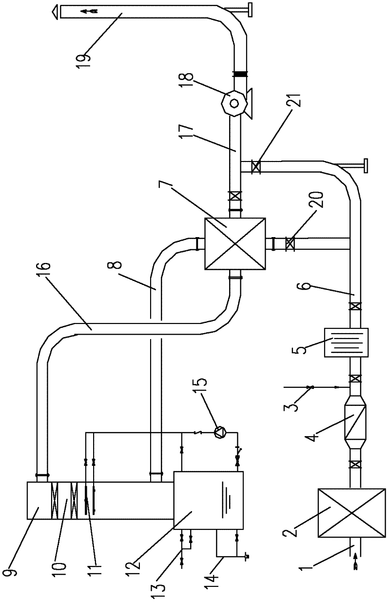
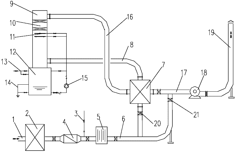
[0029] Example 1, such as figure 1 As shown, a flue gas purification system includes a dust collector 2 installed at the inlet of flue gas 1 after dry and semi-dry deacidification, an induced draft fan 18 and a smoke exhaust chimney 19 . Between the described deduster 2 and the induced draft fan 18, the ammonia injection device 3 for denitrification is set in sequence through the flue, the catalytic reactor 5 for removing dioxin and nitrogen oxides, the reaction of deacidification and white smoke elimination Tower 9; the reaction tower 9 is a washing tower, including a water tank 12 arranged at the bottom of the tower body, a secondary side low-temperature flue 16 for entering flue gas on the tower body, and a secondary side high-temperature flue gas outlet for flue gas at the upper part of the tower body. A flue 17; at least one set of spraying device 11 is arranged on the upper part of the tower body; a filler 10 (such as stone) that absorbs heat and blocks water smoke is al...

Embodiment 2

[0031] Embodiment 2, on the basis of the technical solution of Embodiment 1, in order to increase the exhaust gas temperature and facilitate the catalytic reaction of the flue gas, a heater 4 for flue gas is also arranged between the dust collector 2 and the ammonia injection device 3 . All the other are with embodiment 1. A particularly preferred flue gas heater is an electric heater.

Embodiment 3

[0032] Embodiment 3, on the basis of the technical scheme of embodiment 1 or 2, in order to reduce the temperature of the flue gas entering the reaction tower 9, an isolated double-smoke-smoke heat exchange is set between the catalytic reactor 5 and the reaction tower 9 device 7; the primary high-temperature flue 6 at the outlet of the catalytic reactor 5 is connected to the primary low-temperature flue 8 connected to the reaction tower 9 through the first valve 20 and the isolated double-smoke-smoke heat exchanger 7 . Further, the low-temperature flue 18 on the secondary side connected to the reaction tower is connected to the high-temperature flue 17 on the secondary side through the isolated double-smoke-smoke heat exchanger 7 . All the other are with embodiment 1 or 2. The inner wall of the smoke-smoke heat exchanger is treated with anti-corrosion treatment (such as setting ceramic materials) to prevent low-temperature corrosion.


PUM


Abstract

A flue gas purifying system comprises a deduster arranged on a flue gas inlet, and induced draught fan and a smoke evacuation chimney. An ammonia spraying apparatus for denitration, a catalytic converter for depriving dioxin and nitrogen oxide, and a reaction tower for depickling and eliminating white smoke are successively arranged between the deduster and the induced draught fan and are communicated by the gas flue. The reaction tower is a washing tower comprising a water tank arranged on the tower bottom, a secondary low temperature flue arranged on the tower body, a secondary high temperature flue for flue gas discharge arranged on an upper part of the tower body. The upper part of the internal tower is provided with at least a set of spray apparatuses, which are equipped with filling materials for heat absorption and Water flue gas obstruction on an upper part thereof; the water tank and the spraying apparatus connect with a circulating pump arranged on the pipe; and the water tank is also equipped with a water supplement apparatus and a pollution discharge apparatus. Besides, a flue gas heater can be arranged on a deduster outlet, and a smoke-smoke heat exchanger can be arranged between the catalytic converter and the reaction tower. The system of the invention can solve problems in a flue gas purifying system, such as large amount of fly ash, dioxin decomposition, large demand of ammonia water and visual pollution.

Description

technical field [0001] The invention relates to a flue gas purification system, in particular to a flue gas purification system for removing dioxins and nitrogen oxides, deacidification and white smoke in a garbage incineration device. Background technique [0002] After incineration of domestic waste, a large amount of flue gas will be produced, and the flue gas not only contains a large amount of acid gas (mainly HCL, SO 2 ), dust particles, heavy metals, dioxins and other pollutants, and also contains a lot of water vapor. Among them, dioxin is highly toxic and mainly exists in flue gas and fly ash. Dioxin in flue gas has an impact on the surrounding environment. Fly ash is a hazardous waste and the treatment cost is high. In addition, the water vapor in the smoke in winter is also visual pollution. It looks like white water mist during the day and black water mist at night. At present, common flue gas purification systems include: SNCR denitration (spraying ammonia wat...

Claims


Application Information

Patent Timeline
Patent Type & Authority Applications(China)
IPC IPC(8): B01D53/78B01D53/86B01D53/60B01D53/68B01D53/72F23J15/00
CPCY02A50/20
Inventor 吴凯秦志坚郑文胜王立陈卫荣
Owner 光大环保能源(苏州)有限公司
Why Eureka
Try Eureka