
A method of manufacturing a semiconductor device

A manufacturing method and semiconductor technology, applied in semiconductor devices and other directions, can solve problems such as interface layer thickening, and achieve the effect of reducing EOT

Active Publication Date: 2011-12-28
锐立平芯微电子(广州)有限责任公司
View PDF5 Cites 18 Cited by
  • Summary
  • Abstract
  • Description
  • Claims
  • Application Information

AI Technical Summary

Problems solved by technology

However, in high-k / metal gate processes, the interfacial layer becomes thicker during the annealing process due to the necessary annealing process
However, due to the very serious short-channel effect in CMOS devices below 45nm, a gate dielectric with an EOT (Equivalent Oxide Thickness) of no more than 1nm is required to improve the control ability of the channel, so a thick interface layer SiO 2 is unacceptable

Method used


Image

  • A method of manufacturing a semiconductor device
  • A method of manufacturing a semiconductor device
  • A method of manufacturing a semiconductor device

Examples


Embodiment Construction

[0008] The present invention generally relates to methods of fabricating semiconductor devices. The following disclosure provides many different embodiments or examples for implementing different structures of the present invention. To simplify the disclosure of the present invention, components and arrangements of specific examples are described below. Of course, they are only examples and are not intended to limit the invention. Furthermore, the present invention may repeat reference numerals and / or letters in different instances. This repetition is for the purpose of simplicity and clarity and does not in itself indicate a relationship between the various embodiments and / or arrangements discussed. In addition, various specific process and material examples are provided herein, but one of ordinary skill in the art will recognize the applicability of other processes and / or the use of other materials. Additionally, configurations described below in which a first feature is ...


PUM

PropertyMeasurementUnit
Thicknessaaaaaaaaaa
Thicknessaaaaaaaaaa

Abstract

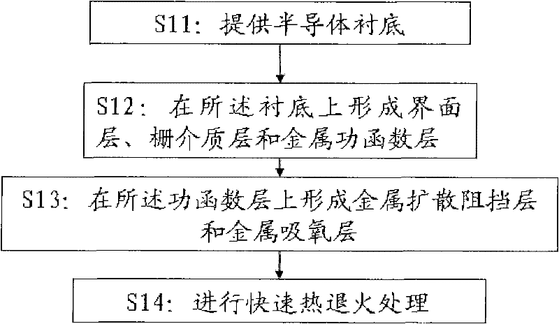
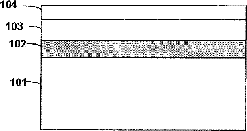
The invention relates to the field of semiconductor manufacturing and provides a method for manufacturing a semiconductor device. The method comprises the following steps: providing a semiconductor substrate; forming an interface layer, a gate dielectric layer and a metal work function layer on the substrate; forming a diffusion barrier layer on the metal work function layer; forming a metal oxygen absorbing layer on the diffusion barrier layer; and carrying out thermal annealing treatment on the device so as to ensure the metal oxygen absorbing layer to absorb the oxygen in the interface layer to reduce the thickness of the interface layer and ensure the diffusion barrier layer to prevent the oxygen absorbing metals in the metal oxygen absorbing layer from being diffused into the metal work function layer. By adopting the method, the oxygen absorbing metals can be prevented from being diffused into the work function layer and / or gate dielectric layer while the thickness of the interface layer is reduced, thus reducing the equivalent oxide thickness under the premise of not affecting the threshold voltage of the device.

Description

technical field [0001] The present invention generally relates to a manufacturing method of a semiconductor device, and in particular, relates to a threshold voltage control method of a gate region of a CMOS device. Background technique [0002] For decades in the development of microelectronics technology, logic chip manufacturers have been using SiO2 when manufacturing MOS devices. 2 As the gate dielectric, heavily doped polysilicon is used as the gate electrode material. However, as feature sizes continue to shrink, SiO in MOS transistors 2 The gate dielectric is approaching its limit. For example, in a 65nm process, SiO 2 The thickness of the gate dielectric has been reduced to 1.2 nanometers, which is about 5 silicon atomic layers thick. If it continues to shrink, the leakage current and power consumption will increase sharply. At the same time, problems such as the diffusion of doped boron atoms caused by the polysilicon gate electrode, the polysilicon depletion ef...

Claims


Application Information

Patent Timeline
IPC IPC(8): H01L21/28
Inventor 韩锴王文武王晓磊马雪丽陈大鹏
Owner 锐立平芯微电子(广州)有限责任公司
Learn More