Main structure

A main structure, concrete structure technology, applied in the direction of structural elements, building components, building structures, etc.

Inactive Publication Date: 2012-01-11
吕怀民 +1
View PDF0 Cites 15 Cited by
  • Summary
  • Abstract
  • Description
  • Claims
  • Application Information

AI Technical Summary

Problems solved by technology

[0011] The purpose of the present invention is to provide a main body structure in order to

Method used


Image

  • Main structure
  • Main structure
  • Main structure

Examples


Embodiment 1

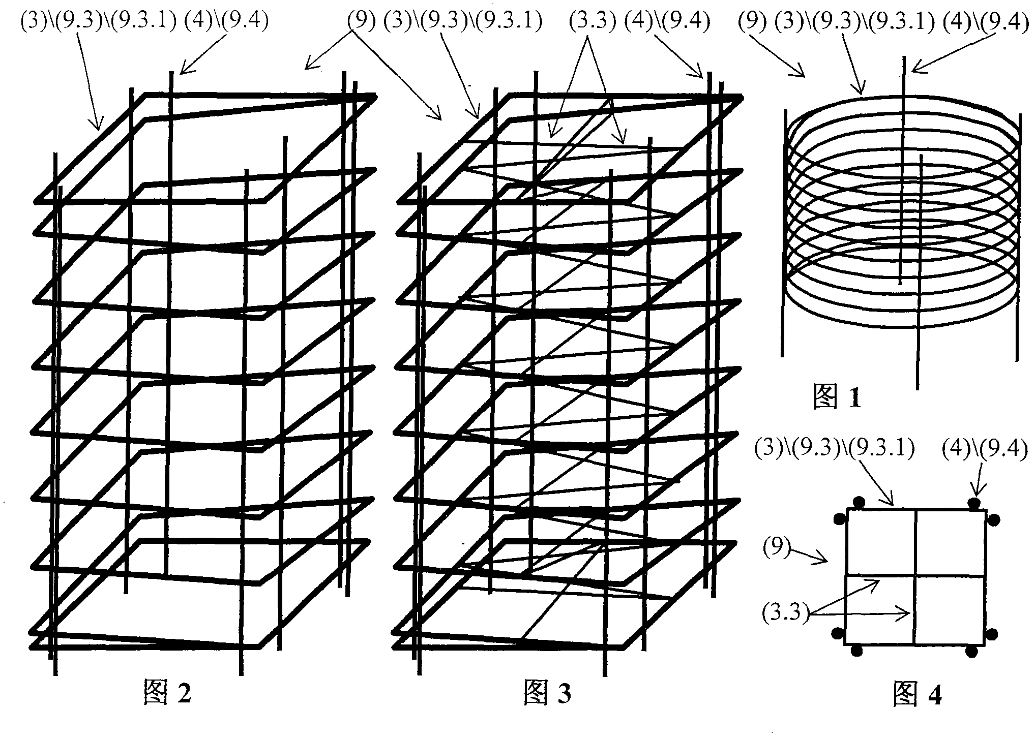
[0199] Example 1. from figure 1 , figure 2 , image 3 with Figure 4 It can be seen that it is a circular or rectangular prefabricated overall stirrup cage frame (9) with node segments of spiral stirrups. It is characterized in that it includes cage spiral stirrups (9.3.1), cage vertical bars (9.4), and the cage stirrups (9.3) and cage vertical bars (9.4) are connected by welding. The diameter of the cage spiral stirrup (9.3.1) is between 1-32 mm; the spacing between the stirrups is between 40-60 mm; Less than 250mm. Steel materials for cage spiral stirrups (9.3.1) and cage vertical bars (9.4) include one of the following combinations: HPB235, HRB335, HRB400, RRB400. The "minimum reinforcement ratio eigenvalue λv" or "volume reinforcement ratio ρv" of the stirrup (3) is greater than the "Code for Design of Concrete Structures" GB50010-2002 or "Code for Seismic Design of Buildings" GB 50010-2002 or "High-Rise Building Structure More than 1.8 times the specified value of...

Embodiment 2

[0200] Example 2. from figure 1 , figure 2 , image 3 with Figure 4 It can be seen that it is a circular or rectangular prefabricated overall stirrup cage frame (9) with node segments of spiral stirrups. It is characterized in that: the cage spiral stirrup (9.3.1) adopts inorganic non-metallic fiber or fiber reinforced composite material (FRP) or advanced composite material (ACM); wherein the inorganic non-metallic fiber includes one of the following materials: basalt fiber , carbon fiber, glass fiber, ceramic fiber. All the other features are the same as in Example 1.

Embodiment 3

[0201] Example 3. from figure 1 , figure 2 , image 3 with Figure 4 It can be seen that it is a circular or rectangular prefabricated overall stirrup cage frame (9) with node segments of spiral stirrups. It is characterized in that: the cage spiral stirrup (9.3.1) adopts a reinforcing material composed of metal material and non-metal fiber material, that is, metal and non-metal fiber composite material (11). All the other features are the same as in Example 1.


PUM

PropertyMeasurementUnit
Thicknessaaaaaaaaaa
Thicknessaaaaaaaaaa
Thicknessaaaaaaaaaa

Abstract

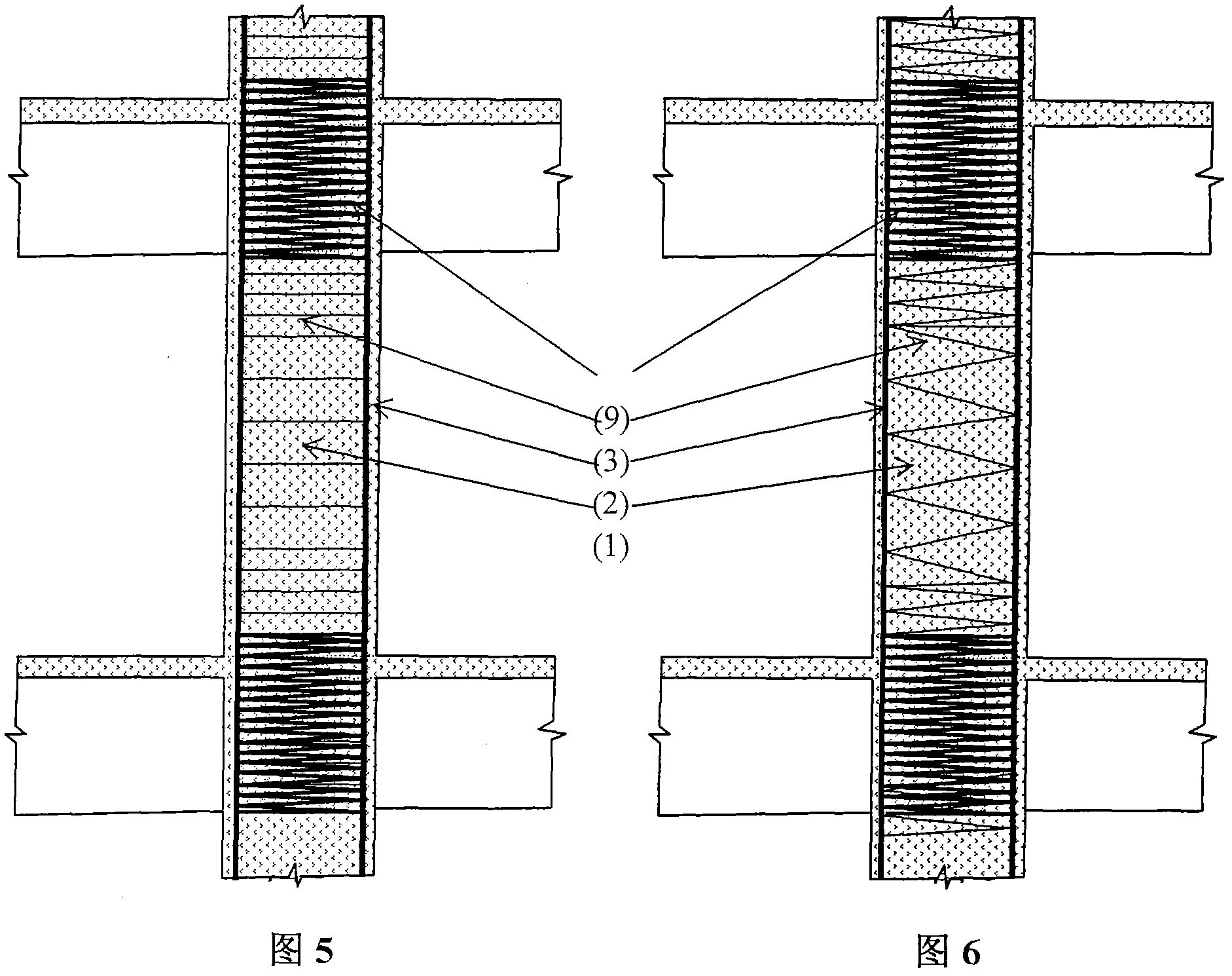
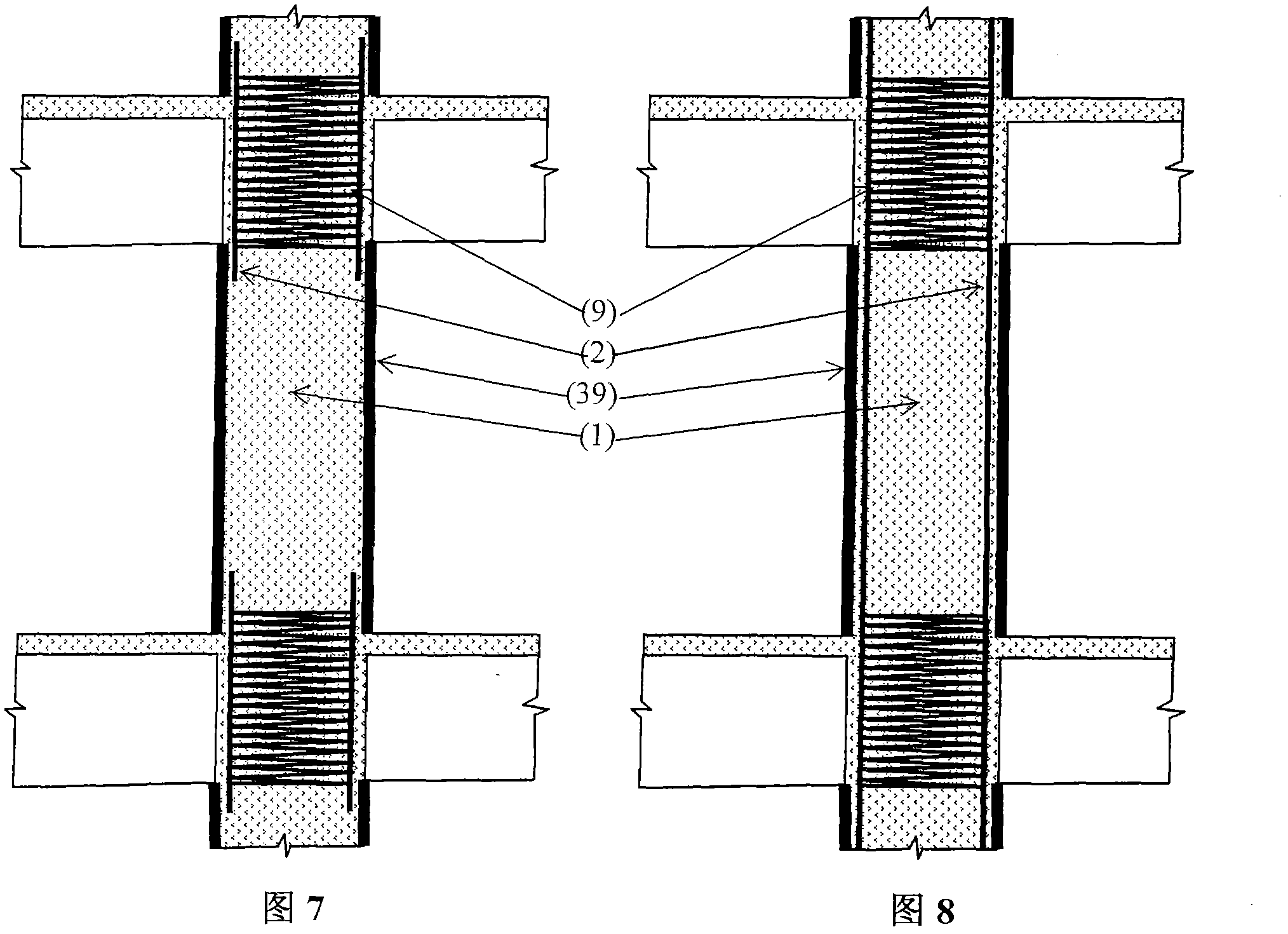
The invention belongs to the field of the civil engineering structure. A main structure adopts the following eleven new structure forms: A) a whole node prefabricated stirrup cage frame, B) a concrete filled steel tube structured stirrup node, C) a prefabricated sleeve, D) an inorganic nonmetal fiber or fiber reinforced plastic material (FRP) or advanced compound material (ACM), E) a metal and nonmetal fiber compound material, F) a greatly increased minimum reinforcement ratio characteristic value Lambda v or volume reinforcement ratio rho v, G) a phase-change heat-absorbing cooling fire-preventing system in a steel structure, H) a water-softening resisting hollow pile foundation having a sealing layer and a sealing body, J) a fastened foundation having a thin steel tube, K) a substitute hoop node, L) a substitute core-filling pile body, and the like. The structure form A), K) and F) are used for solving the problem of the concrete pile soft node; B) is used for solving the problems of softness, high cost and poor fire prevention and corrosion prevention of the concrete filled steel tube structure; C) and E) are used for solving the problem of the fat column body of the reinforced concrete column; G) is used for solving the problems of poor fire prevention and high cost of the steel structure; H) and L) are used for solving the problems of water seepage and softening of the tube pile foundation; and J) is used for solving the problem of fully utilizing rock soil to greatly reduce the construction cost of the foundation.

Description

technical field [0001] The invention relates to a main body structure, which belongs to the structural field of civil construction engineering. Background technique [0002] The main structure of civil engineering engineering includes superstructure and lower foundation; its types mainly include concrete structure, reinforced concrete structure, steel pipe concrete structure, masonry concrete structure, composite fiber concrete structure, steel structure; the main structure includes piles, columns, Rods, walls, beams, slabs, joints main components. The main structure currently has the following six major problems. [0003] 1. In reinforced concrete structures, there is a problem of "soft joints" in column joints. The quality of column joint design and construction is related to the safety of the entire structural system. Theoretically speaking, the rigidity of joints is stronger than that of columns, beams, and slabs, but in actual engineering, the rigidity of joints is t...

Claims


Application Information

Patent Timeline
IPC IPC(8): E04B1/20E04B1/76E04C5/01
CPCY02A30/244
Inventor 吕怀民吕屾
Owner 吕怀民
Why Eureka
Try Eureka